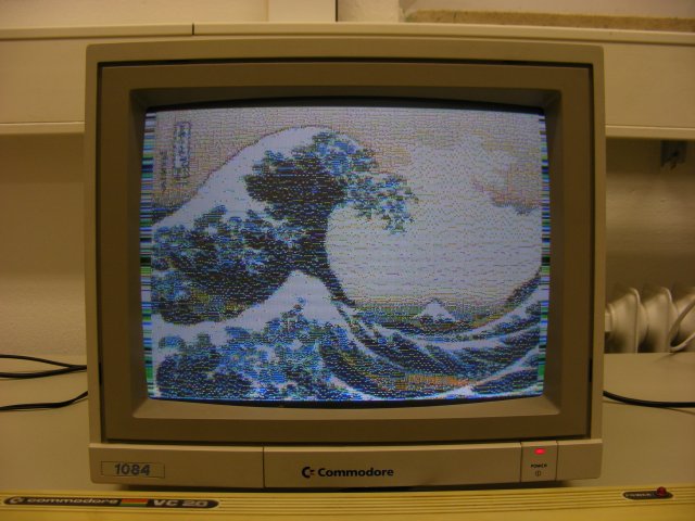
Introducing VFLI for VIC-20: 208x256 pixels in 16 colours!
Posted: Thu Nov 18, 2010 3:20 pm
Hi, y'all!
In the thread '** New Frontiers in VIC-Hires-Graphics, Part 10' I hinted at the possibility to expand the FLI mode presented there (72x256 pixels) to the full screen width of 208 pixels. This is possible with a hardware mod, I've done it, with great help from a friend with that extra experience in soldering work and of course electronics as well, to make this mod a success on the first shot.
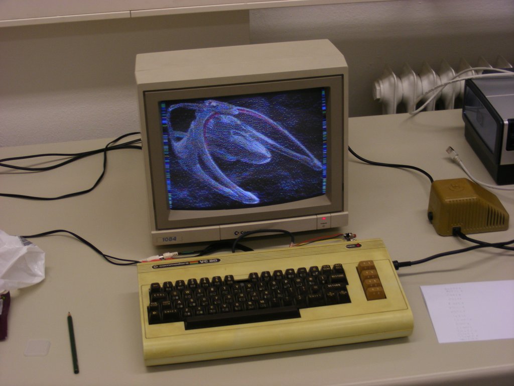
Here's the result. An image of Andromeda Ascendant - which was the first image tried out with the new display system:
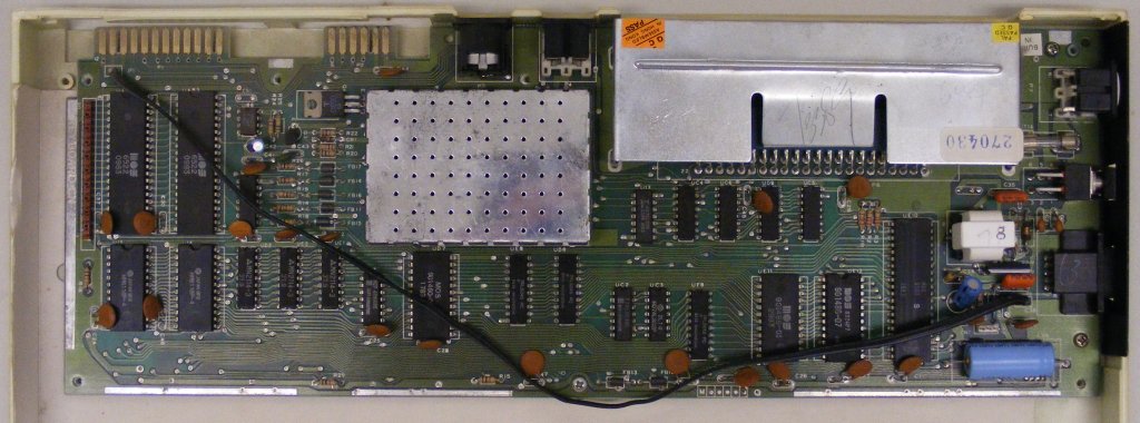
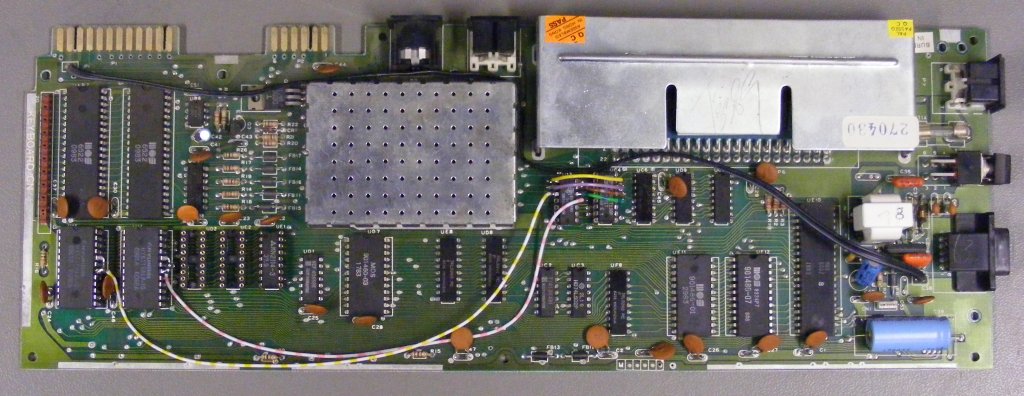
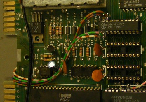
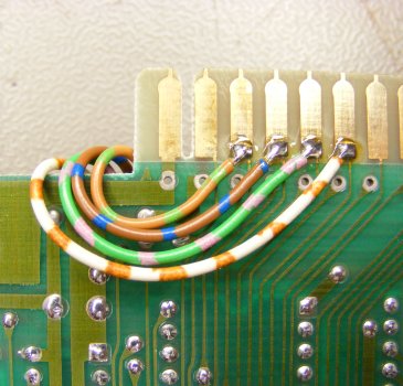
The hardware modification is done in 3 steps on a CR mainboard:
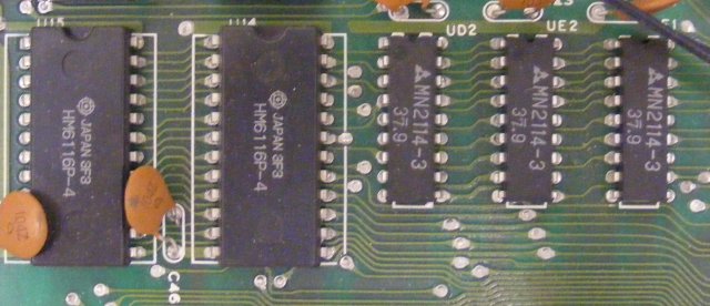
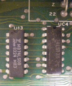
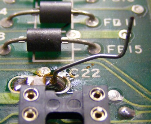
1. At first, all RAM chips and two chips of the select logic are desoldered, and sockets placed instead. This step completed, the chips can be re-inserted to check everything still works.
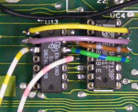
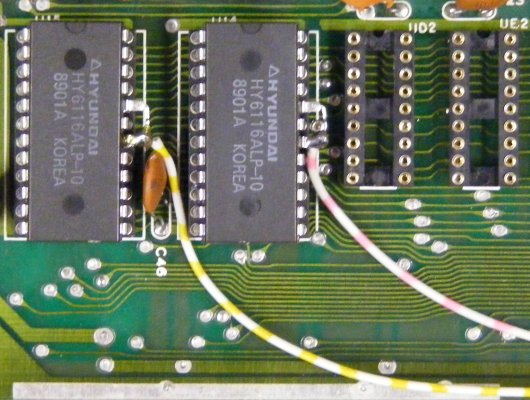
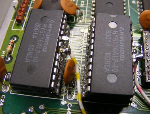
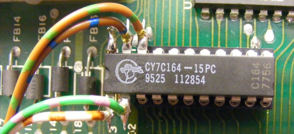
2. Internal RAM is expanded from 5K to 8K. This involves piggy-backing one extra RAM chip on the two existing 2K RAM chips and rewiring some part of the chip select logic. This also allows for an intermediary check.
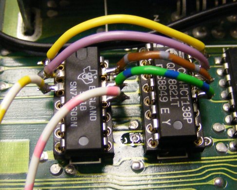
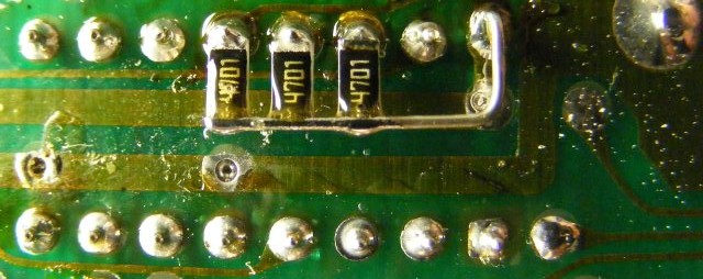
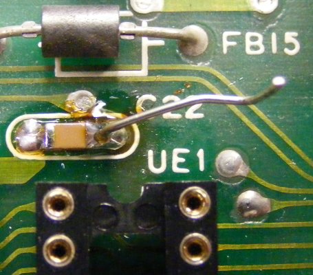
3. The colour RAM is replaced with a chip with 16 times capacity (i.e. 16K x 4 bits). The VFLI display routine then switches banks on each raster line to provide 8x1 attribute cells. The 4 necessary extra address lines are provided on the user port, with Port B of VIA1.
More details to the mod, and d/l links to two *.d64 images containing 30 images will follow shortly.
Cheers,
Michael
In the thread '** New Frontiers in VIC-Hires-Graphics, Part 10' I hinted at the possibility to expand the FLI mode presented there (72x256 pixels) to the full screen width of 208 pixels. This is possible with a hardware mod, I've done it, with great help from a friend with that extra experience in soldering work and of course electronics as well, to make this mod a success on the first shot.
Here's the result. An image of Andromeda Ascendant - which was the first image tried out with the new display system:
The hardware modification is done in 3 steps on a CR mainboard:
1. At first, all RAM chips and two chips of the select logic are desoldered, and sockets placed instead. This step completed, the chips can be re-inserted to check everything still works.
2. Internal RAM is expanded from 5K to 8K. This involves piggy-backing one extra RAM chip on the two existing 2K RAM chips and rewiring some part of the chip select logic. This also allows for an intermediary check.
3. The colour RAM is replaced with a chip with 16 times capacity (i.e. 16K x 4 bits). The VFLI display routine then switches banks on each raster line to provide 8x1 attribute cells. The 4 necessary extra address lines are provided on the user port, with Port B of VIA1.
More details to the mod, and d/l links to two *.d64 images containing 30 images will follow shortly.
Cheers,
Michael