
It is now installed in hundreds of C64 and has exhibited a level of compatibility higher than the SuperPLA V3.
Here are a few logic analyser captures showing clearly there is no "bus contentions" as proclaimed.
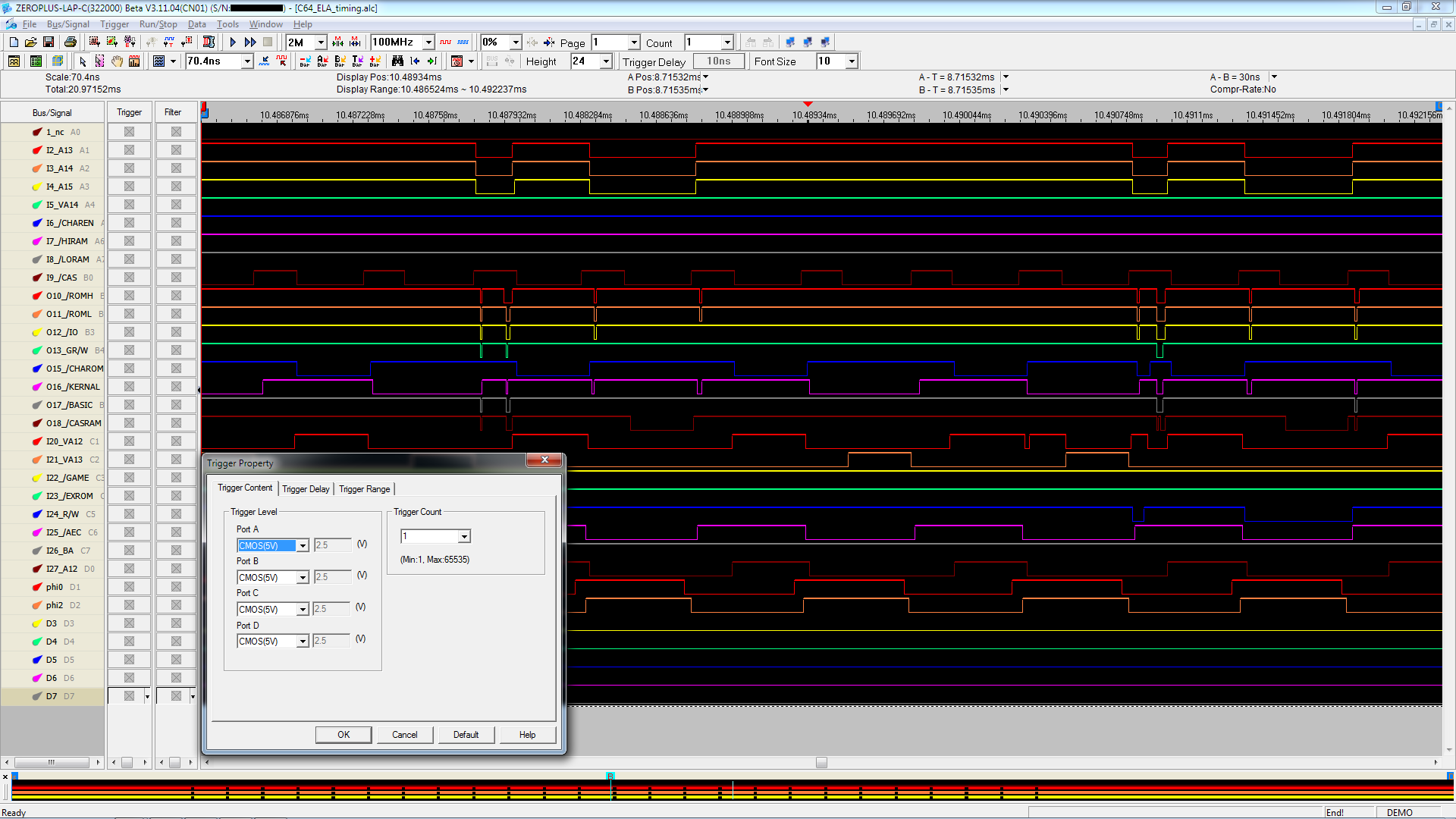
This first capture shows a C64 with board 250466 running with this IC as PLA.

There is one occurence of multiple signaling in this graphic - its a write access to the color SRAM and is therefore part of the normal operations of a C64.
This second capture shows the PLA outputs activity while the cartridge Super Zaxxon from SEGA is running in demo mode.

As I said and can now prove, if we are to assume the circuit obtained is genuine then the only way to obtain the type of outputs that can be seen on the graphic obtained by the friend of Mr. Schönfeld is to cheat with numbers - set the threshold level unreasonably high.

I believe this is proof enough that this is a complete fabrication. An easy one too.
It cannot be limited by the PLA that I provide because it cannot be limited by ANY PLA at all. Even Commodore's own made PLAs can, for very brief periods of time will pull two select lines low. This problem can be compounded if very fast ICs are used as kernal replacements or in cartridges.wiesel wrote:Now that we know that the number of CMOS devices on the same data bus cannot be limited by the PLA that you are providing, you need to guarantee that your PLA device will never pull two (or more) select lines low at the same time.
This problem is alleviated when the PLA used will generate a brief "dead time" when switching from one select line to another. Something the ST PROM does. Not so with the 82S100, the 7700 and the 8700.
The measurements you provided were clearly fabricated and I was able to do the same thing.As measurements by Tommi and me are showing, this cannot be guaranteed with an EPROM-based PLA.
ADDED EDIT:
The original picture concerning the M27C512-90B6 (apparently purchased from UT Source) behavior as a PLA was changed.
While the original (link here ) did not show the threshold voltage or capture rate, the new capture shows a capture rate of 100MHz and a threshold voltage of 2.5 volts.
Although this setting is still inadequate for TTL-LS technology (Skoe used 1.3 volts in his analysis called "PLA Dissected"), it shows multiple signaling that nether Skoe, who also used a 100MHz capture rate, nor myself using the Intronix Logicport at a capture rate of 500MHz could mange to find at various threshold levels as seen above.
This leaves only one possibility AFAIK, the person who did the capture for Jens Schönfeld, assuming this person was honest, obtained circuits
that were counterfeit.
I did notice in the past that the circuits sold by UT Source have a type of pin 1 indicator notch that is quite different from the units I have purchased from Mouser between 2008 and 2011. Mouser certifies the components sold are genuine.
Jens Schönfeld, surprisingly did defend a threshold level of 4.7 volts as being adequate. Since the previously posted oscilloscope capture clearly indiquate all types of Commodore original PLAs don't signal above 4.3 volts, I find this claim quite troublesome. Skoe found numbers that are even lower.
