
I've been looking into trying out this project from the Vic 20 programmers reference guide.
Do these pokes effect running inteeupts? It appears that they affect the interupt flag and shift registor. Would a program running this disable me from running other programs be it irq, nmi or basic.
I would like to run the Vic as a music module. Using the Vics 4 main voices as a loop box controlled by the lower 2 rows of the keyboard and the user port voice as a lead synth controlled by the upper rows.
User port sound
Moderator: Moderators

Re: User port sound
The default settings of the IER that the KERNAL sets up don't include the shift register bit and none of the interrupt code checks the matching IFR bit.
-
armypavarmy
- Vic 20 Hobbyist
- Posts: 107
- Joined: Wed Oct 02, 2013 1:54 am
- Location: Italy
Re: User port sound
Hello
I have done all the tests for some time
for sound on CB2.
The result has been very disappointing.
I can assure you.
I have material and documentation available
if anyone is interested in trying again.
Greetings Armando
I have done all the tests for some time
for sound on CB2.
The result has been very disappointing.
I can assure you.
I have material and documentation available
if anyone is interested in trying again.
Greetings Armando
Re: User port sound
Disappointing how?armypavarmy wrote: ↑Sat Apr 18, 2020 6:46 am Hello
I have done all the tests for some time
for sound on CB2.
The result has been very disappointing.
I can assure you.
I have material and documentation available
if anyone is interested in trying again.
Greetings Armando
I'm expecting a raw electronic sound.
R'zo
I do not believe in obsolete...
I do not believe in obsolete...
Re: User port sound
To say the least I'm interested. Am going to start playing with it in the next few days. I am curious to see what your results were.armypavarmy wrote: ↑Sat Apr 18, 2020 6:46 am Hello
I have done all the tests for some time
for sound on CB2.
The result has been very disappointing.
I can assure you.
I have material and documentation available
if anyone is interested in trying again.
Greetings Armando
R'zo
I do not believe in obsolete...
I do not believe in obsolete...

Re: User port sound
Could be a nice exercise. And sounds not bad - if armypavarmy meant this. 1 bit pulse width modulation sounds like an C64 SID - premise you are dealing with machine code.
BTW: there are some undocumented sound features of the vic 20 from stock. I will explain at right time...
But back to topic, if you're already are there to connect the user port to an a amplifier, why do not doing it at the right way - furthermore with superior sound quality?
User port has as known 8 in / out lines condensed in 1 byte, which address - if switched as output with the DDR - gives the possibility to output two 4 bit samples at same time = S T E R E O!
And belive me - it sounds great!
Simply feed this monster from the screenshot with 1 byte proper to nibbles packed sample - and be astonished .
.
Unfortunately I forgot where I got the the circuit from an lost the driver, some hardware cracks out there should be anyhow able to reverse engineer it from my picture - no active components were used. On the soldering side there are only the straight connections to the uport.
The code for sending the samples to port should be simple to implement - but there are some strict requirements - it should be stable and must have the same playback frequency as sampling frequency from whatever source sample was - this implies the time between playing 2 bytes of the samples cycle precise - at leat for 256 bytes sample stream from memory. So the sample will sound very clean. The irregularity for incrementing the zero page high byte pointer can be left uncared - weighting a such sort of routing is still possible, but leads to an huge play back routine.
Bye for now, stay healthy!
BTW: there are some undocumented sound features of the vic 20 from stock. I will explain at right time...
But back to topic, if you're already are there to connect the user port to an a amplifier, why do not doing it at the right way - furthermore with superior sound quality?
User port has as known 8 in / out lines condensed in 1 byte, which address - if switched as output with the DDR - gives the possibility to output two 4 bit samples at same time = S T E R E O!
And belive me - it sounds great!
Simply feed this monster from the screenshot with 1 byte proper to nibbles packed sample - and be astonished
Unfortunately I forgot where I got the the circuit from an lost the driver, some hardware cracks out there should be anyhow able to reverse engineer it from my picture - no active components were used. On the soldering side there are only the straight connections to the uport.
The code for sending the samples to port should be simple to implement - but there are some strict requirements - it should be stable and must have the same playback frequency as sampling frequency from whatever source sample was - this implies the time between playing 2 bytes of the samples cycle precise - at leat for 256 bytes sample stream from memory. So the sample will sound very clean. The irregularity for incrementing the zero page high byte pointer can be left uncared - weighting a such sort of routing is still possible, but leads to an huge play back routine.
Bye for now, stay healthy!
- Attachments
-
Last edited by Noizer on Fri May 15, 2020 11:14 am, edited 2 times in total.
Valid rule today as earlier: 1 Byte = 8 Bits
-._/classes instead of masses\_.-
-._/classes instead of masses\_.-
Re: User port sound
Its just an R2R ladder, really trivial  This one was kinda common at some point: https://en.wikipedia.org/wiki/Covox_Speech_Thing (there was a userport variant too). I'd go for 8bit mono instead of 4bit stereo, as more bits greatly improve the quality
I'm just a Software Guy who has no Idea how the Hardware works. Don't listen to me.
Re: User port sound
The one in Noizer's post seems a bit strange though. There are 8 diodes and not so many resistors. Is that a single 4-bit R2R switched by some diode trick perhaps?groepaz wrote: ↑Fri Apr 24, 2020 3:45 am Its just an R2R ladder, really trivial
-
Mike

- Herr VC
- Posts: 4841
- Joined: Wed Dec 01, 2004 1:57 pm
- Location: Munich, Germany
- Occupation: electrical engineer
Re: User port sound
The user port dongle in Noizer's post is not a R2R-D/A-Converter.
For the amplitude weightings of the different bits, it uses 4 different resistors to form current sinks with a common shunt resistor which then makes a voltage from the current. The diodes are there to decouple the current sinks.
This design requires somewhat more precisely valued resistors and only works well when the common shunt resistor is relatively small compared to the current sink resistors. You'll also want roughly 1 Vpp for Audio Out. As a rough guess:
When all bits are 1, no current flows from +5V into the resistors. Node X is also at +5V.
When a bit is 0, the node between respective diode and resistor is at around +1V. With all bits 0, the total resistance then is 320 Ohm, which forms a voltage divider between +5V, X, and +1V: (5V - X) / (X - 1V) = 100 Ohm / 320 Ohm => X ~= 4.05 V.
So we have the 1 Vpp for the two extreme values. The capacitor provides the capacitive coupling for the audio output, and should be chosen around 200 µF.
With just bit 3 on, the 3 remaining 'active' resistors form a total resistance of 686 Ohm => (5V - X) / (X - 1V) = 100 Ohm / 686 Ohm => X ~= 4.49 V. With bits 0, 1, 2 on, the single 'active' resistor has 600 Ohm => (5V - X) / (X - 1V) = 100 Ohm / 600 Ohm => X ~= 4.43 V. Here's the rest of the voltages at node X:
The input resistance of the connected sound amplifier should be at least around 10 KOhm. And, for higher bit resolutions, a R2R-ladder is definitely the better choice.
Edit: the polarity of the diodes in Noizer's photo would indicate, that the VIA outputs are actually used as current sources. This also works, because port B of the VIA has a switching FET to the positive rail. Normally, with NMOS or TTL outputs, their use as current sink is preferred though.
For the amplitude weightings of the different bits, it uses 4 different resistors to form current sinks with a common shunt resistor which then makes a voltage from the current. The diodes are there to decouple the current sinks.
This design requires somewhat more precisely valued resistors and only works well when the common shunt resistor is relatively small compared to the current sink resistors. You'll also want roughly 1 Vpp for Audio Out. As a rough guess:
Code: Select all
                           A +5V
                           |
                           |
                           |
                           |
                          +-+
                          | |
                          | | 100
                          | |
                          +-+
                           |
                           |      +
Bit             600        |
              +-----+      |X     |  |
 3 o----|<|---|     |------+------|  |------o Audio Out
              +-----+      |      |  |
                           |
                1K2        |
              +-----+      |
 2 o----|<|---|     |------+
              +-----+      |
                           |
                2K4        |
              +-----+      |
 1 o----|<|---|     |------+
              +-----+      |
                           |
                4K8        |
              +-----+      |
 0 o----|<|---|     |------+
              +-----+
When a bit is 0, the node between respective diode and resistor is at around +1V. With all bits 0, the total resistance then is 320 Ohm, which forms a voltage divider between +5V, X, and +1V: (5V - X) / (X - 1V) = 100 Ohm / 320 Ohm => X ~= 4.05 V.
So we have the 1 Vpp for the two extreme values. The capacitor provides the capacitive coupling for the audio output, and should be chosen around 200 µF.
With just bit 3 on, the 3 remaining 'active' resistors form a total resistance of 686 Ohm => (5V - X) / (X - 1V) = 100 Ohm / 686 Ohm => X ~= 4.49 V. With bits 0, 1, 2 on, the single 'active' resistor has 600 Ohm => (5V - X) / (X - 1V) = 100 Ohm / 600 Ohm => X ~= 4.43 V. Here's the rest of the voltages at node X:
Code: Select all
  3    2    1    0      X

  0    0    0    0    4.05 V
  0    0    0    1    4.10 V
  0    0    1    0    4.15 V
  0    0    1    1    4.20 V
  0    1    0    0    4.25 V
  0    1    0    1    4.31 V
  0    1    1    0    4.37 V
  0    1    1    1    4.43 V
  1    0    0    0    4.49 V
  1    0    0    1    4.56 V
  1    0    1    0    4.62 V
  1    0    1    1    4.69 V
  1    1    0    0    4.76 V
  1    1    0    1    4.84 V
  1    1    1    0    4.92 V
1 1 1 1 5.00 VEdit: the polarity of the diodes in Noizer's photo would indicate, that the VIA outputs are actually used as current sources. This also works, because port B of the VIA has a switching FET to the positive rail. Normally, with NMOS or TTL outputs, their use as current sink is preferred though.
Re: User port sound
ugh this (probably literally) sounds even worse than what i thought =)
I'm just a Software Guy who has no Idea how the Hardware works. Don't listen to me.
-
Mike
- Herr VC
- Posts: 4841
- Joined: Wed Dec 01, 2004 1:57 pm
- Location: Munich, Germany
- Occupation: electrical engineer
Re: User port sound
Well, the output characteristic is slightly non-linear, but it's not too bad. It might even result in a tube-like sound.groepaz wrote:ugh this (probably literally) sounds even worse than what i thought =)
Here's now the correct reversed schematic:Mike wrote:[T]he polarity of the diodes in Noizer's photo would indicate, that the VIA outputs are actually used as current sources. [...]
Code: Select all
                1K
              +-----+
 3 o----|>|---|     |------+
              +-----+      |
                           |
             2K / 2K2      |
              +-----+      |
 2 o----|>|---|     |------+
              +-----+      |
                           |
                3K9        |
              +-----+      |
 1 o----|>|---|     |------+
              +-----+      |
                           |      +
                8K2        |
              +-----+      |X     |  |
 0 o----|>|---|     |------+------|  |------o Audio Out
              +-----+      |      |  |
                           |
                           |
                           |
                          +-+
                          | |
                          | | 470
                          | |
                          +-+
                           |
                           |
                           |
---+---Given that, here are the actual resulting voltages for node X (with the 2K resistance - the 2K2 version is slightly different):
Code: Select all
  3    2    1    0      X

  0    0    0    0    0.00 V
  0    0    0    1    0.11 V
  0    0    1    0    0.22 V
  0    0    1    1    0.30 V
  0    1    0    0    0.38 V
  0    1    0    1    0.45 V
  0    1    1    0    0.52 V
  0    1    1    1    0.58 V
  1    0    0    0    0.64 V
  1    0    0    1    0.69 V
  1    0    1    0    0.74 V
  1    0    1    1    0.79 V
  1    1    0    0    0.83 V
  1    1    0    1    0.87 V
  1    1    1    0    0.90 V
1 1 1 1 0.94 VNo big issue when the sample output is done in an interrupt routine (for example NMI from a VIA timer).Noizer wrote:[The code] should be stable and must have the same playback frequency as sampling frequency from whatever source sample was - this impl[ies] the time between playing 2 bytes of the samples to be [precise] at the clock cycle
-
eslapion

- ultimate expander
- Posts: 5458
- Joined: Fri Jun 23, 2006 7:50 pm
- Location: Canada
- Occupation: 8bit addict
Re: User port sound
Back in late 1984, I did type in the basic program in the PRG and it generated beautiful square wave music worthy of the most expensive arcade machines of the day.
Unlike the VIC's normal sound coming out from the Audio/video port and therefore from the 6560/61, the square wave sounded incredibly clean when I connected the user port's CB2 to a decent audio amplifier.
In hindsight, there is a problem with the square wave generated by any MOS 6522; it's asymmetric. That's because the outputs of any NMOS chip is low impedance when pulled low and high impedance when pulled high. To get a really good quality square wave, you'd need a CMOS version of the 6522 and we all know the popular Rockwell R65C22 has a problem sharing interrupt because it uses a totem pole output.
The solution, I believe, would be to use the W65C22N from Western Design Center. It also happens to have a fixed shift register.
Be normal.
-
Mike
- Herr VC
- Posts: 4841
- Joined: Wed Dec 01, 2004 1:57 pm
- Location: Munich, Germany
- Occupation: electrical engineer
Re: User port sound
Not as asymmetric in the given case as you might think - this is from page 3 of the 6522 datasheet:eslapion wrote:In hindsight, there is a problem with the square wave generated by any MOS 6522; it's asymmetric. That's because the outputs of any NMOS chip is low impedance when pulled low and high impedance when pulled high. [...]
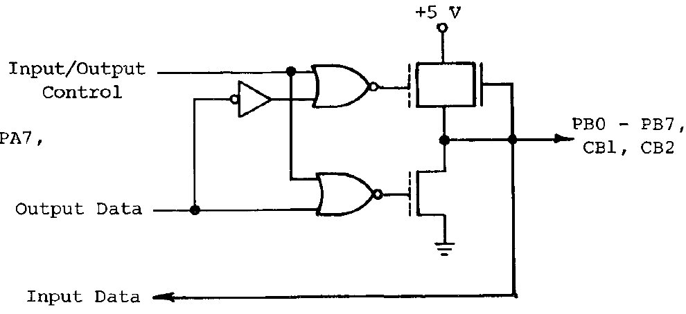
Here, PB0..7, CB1 and CB2 have an additional FET connected to +5V, so this *is* a totem-pole output. Otherwise, Noizer's user port dongle would hardly work at all.
But in general, you are right regarding NMOS and TTL outputs: they can hardly source current (rule of thumb, not much more than around 40 µA at high level) but rather easily sink current (at least 1.6 mA at low level). That's why I first came up with the current sinking version.
Re: User port sound
so who provides the VICE patch? :=P
I'm just a Software Guy who has no Idea how the Hardware works. Don't listen to me.
-
Mike
- Herr VC
- Posts: 4841
- Joined: Wed Dec 01, 2004 1:57 pm
- Location: Munich, Germany
- Occupation: electrical engineer
Re: User port sound
This possibly only gets urgent if any of the designated audio replay programs ever pop up:groepaz wrote:so who provides the VICE patch? :=P
That being said, I could make a reproduction of Noizer's dongle (possibly with some extra buffering to protect the VIA and also provide amplification/filtering on the output side) and produce some simple sound demos for it ... however half the user port of my VIC-20 is already occupied by the VFLI mod.Noizer wrote:Unfortuna[t]ely I forgot where I got the the circuit from an[d] lost the driver, [...]