I have a C2N for Scott Adams save files
Repurposing a Super Expander (or 3K RAM)
Moderator: Moderators
-
chysn

- Vic 20 Scientist
- Posts: 1205
- Joined: Tue Oct 22, 2019 12:36 pm
- Website: http://www.beigemaze.com
- Location: Michigan, USA
- Occupation: Software Dev Manager
Re: Repurposing a Super Expander
VIC-20 Projects: wAx Assembler, TRBo: Turtle RescueBot, Helix Colony, Sub Med, Trolley Problem, Dungeon of Dance, ZEPTOPOLIS, MIDI KERNAL, The Archivist, Ed for Prophet-5
WIP: MIDIcast BASIC extension
he/him/his
WIP: MIDIcast BASIC extension
he/him/his
-
chysn
- Vic 20 Scientist
- Posts: 1205
- Joined: Tue Oct 22, 2019 12:36 pm
- Website: http://www.beigemaze.com
- Location: Michigan, USA
- Occupation: Software Dev Manager
Re: Repurposing a Super Expander
The 3K RAM host board has this extra slot, but all of the holes were soldered over. So the first step was to clear those out. I used a soldering iron and a desoldering spring-loaded vacuum pump to get the solder out of the holes for the PROM and the 100nF capacitor.
The next step is getting the chip off the VICMon PCB. I'm sure that there are better tools for this job than the pump I'm using, because it's slow going. I've got many pins free (or at least free-looking), but others are pretty stubborn, and the chip doesn't seem like it's ready to budge any time soon. I have to stop for the night so that I don't go insane.
VIC-20 Projects: wAx Assembler, TRBo: Turtle RescueBot, Helix Colony, Sub Med, Trolley Problem, Dungeon of Dance, ZEPTOPOLIS, MIDI KERNAL, The Archivist, Ed for Prophet-5
WIP: MIDIcast BASIC extension
he/him/his
WIP: MIDIcast BASIC extension
he/him/his
-
Mike

- Herr VC
- Posts: 4841
- Joined: Wed Dec 01, 2004 1:57 pm
- Location: Munich, Germany
- Occupation: electrical engineer
Re: Repurposing a Super Expander
Apply *extra* solder to all pins of the chip to make it movable.chysn wrote:The next step is getting the chip off the VICMon PCB. I'm sure that there are better tools for this job than the pump I'm using, because it's slow going. I've got many pins free (or at least free-looking), but others are pretty stubborn, [...]
Then, with the soldering side of the PCB facing upwards, heat up the iron slightly more and then sweep across one pin row to melt all the solder in that row. From below, *gently* pull that side of the chip. Repeat with the other row.
When you repeat that process, you eventually come to the point that the chip pins become level with the PCB. Then remove all solder with the pump or solder wick. Most pins should come free. Selectively apply heat to those pins that don't.
As for better tools, there are wide solder tips which can apply heat to multiple pins without the need to sweep across the pin row. Alternatively, a hot air gun can also work wonders. Just apply the hot air to all pins until the solder is melted completely and then extract the chip from below. If you need to extract a single part from a more populated PCB, shield off the other parts with aluminum foil.
Good Luck!
-
chysn
- Vic 20 Scientist
- Posts: 1205
- Joined: Tue Oct 22, 2019 12:36 pm
- Website: http://www.beigemaze.com
- Location: Michigan, USA
- Occupation: Software Dev Manager
Re: Repurposing a Super Expander
Finishing The Job
@Mike and @eslapion, thank you so much for all your help in this project. It has been invaluable, seriously.
I sort of discovered a technique for removing the chip. It takes a ton of patience, but once I practiced it for a while, it became very reliable. I realized that most of the time we don't want solder joints to fail, but when they do it's often because of physical stress. Once I got most of the solder sucked away, I was sometimes left with a tiny film that seemed resistant to further sucking as well as wicking. So I'd heat the pad on the component side, as usual; when the solder melted, I'd start flexing the pin on the other side inward--very, very gently--with my fingernail. I'd then move the iron away while still flexing the pin. When the remaining solder cooled, I'd be left with a cold solder joint. If I was still able to flex the pin after this, I'd move to the next pin. If not, I'd do another suck or two and try again. In about an hour, I had all the pins flexing freely in their holes, and I could pry the chip out with a spudger.
(Note: You can tell by sound whether a pin is sufficiently desoldered. Flex it inward with a fingernail, then let your fingernail slide away from the pin, like you're plucking a guitar string. A free pin makes a high-pitched sustained pinging sound. A pin that's not free makes a short low-pitched click. Don't even think about trying to remove the chip until every single pin rings like a miniature kalimba.)
A few of the pins were slightly bent, and it took a little work to get the chip into its new host. I don't have a pin straightener, so I just eyeballed it. I inserted one side just barely into the holes. On the other side, I applied just enough inward pressure on each pin so that I could sort of pop the remaining pins into the holes. There was a nice little clicking sound that let me know that each pin had hit its mark.
Once the chip was in, I soldered in a new 104 (100nF) ceramic capacitor. I cut the Block 1 jumper with an X-Acto knife, and tested with a meter to make sure that it was open. Then I shorted the Block 3 jumper. Then I finished up by soldering all of the pins on the chip. (Note: This picture was taken before I changed the jumpers).
Then it was time to test. I kept the soldering iron hot just in case I had to go back to the lab. But everything worked as expected:
Finally, I closed up. I do less and less damage each time I open and re-close a cartridge, so I had a pretty good level of confidence here. I decided to use the Machine Language Monitor label. However, I was putting a 3K RAM board into this case. Usually, small PBCs are supported by a couple little tabs near the middle of the cartridge case bottom. The 3K PCB is bigger, so these tabs are cut out, and the PCB is supported by tabs near the back. So I used the Machine Language Monitor cartridge top and the 3K RAM cartridge bottom, so I didn't need to break anything unnecessarily.
And that's the project! Thanks again for everyone who helped. This is a great online community.
@Mike and @eslapion, thank you so much for all your help in this project. It has been invaluable, seriously.
I sort of discovered a technique for removing the chip. It takes a ton of patience, but once I practiced it for a while, it became very reliable. I realized that most of the time we don't want solder joints to fail, but when they do it's often because of physical stress. Once I got most of the solder sucked away, I was sometimes left with a tiny film that seemed resistant to further sucking as well as wicking. So I'd heat the pad on the component side, as usual; when the solder melted, I'd start flexing the pin on the other side inward--very, very gently--with my fingernail. I'd then move the iron away while still flexing the pin. When the remaining solder cooled, I'd be left with a cold solder joint. If I was still able to flex the pin after this, I'd move to the next pin. If not, I'd do another suck or two and try again. In about an hour, I had all the pins flexing freely in their holes, and I could pry the chip out with a spudger.
(Note: You can tell by sound whether a pin is sufficiently desoldered. Flex it inward with a fingernail, then let your fingernail slide away from the pin, like you're plucking a guitar string. A free pin makes a high-pitched sustained pinging sound. A pin that's not free makes a short low-pitched click. Don't even think about trying to remove the chip until every single pin rings like a miniature kalimba.)
Once the chip was in, I soldered in a new 104 (100nF) ceramic capacitor. I cut the Block 1 jumper with an X-Acto knife, and tested with a meter to make sure that it was open. Then I shorted the Block 3 jumper. Then I finished up by soldering all of the pins on the chip. (Note: This picture was taken before I changed the jumpers).
VIC-20 Projects: wAx Assembler, TRBo: Turtle RescueBot, Helix Colony, Sub Med, Trolley Problem, Dungeon of Dance, ZEPTOPOLIS, MIDI KERNAL, The Archivist, Ed for Prophet-5
WIP: MIDIcast BASIC extension
he/him/his
WIP: MIDIcast BASIC extension
he/him/his
-
Mike
- Herr VC
- Posts: 4841
- Joined: Wed Dec 01, 2004 1:57 pm
- Location: Munich, Germany
- Occupation: electrical engineer
Re: Repurposing a Super Expander (or 3K RAM)
Nice! That to say: Achievement unlocked! 
Some time ago I wrote a primer for VICMON here in Denial, maybe you'll find some interesting techniques there.
And here's my current setup for low-level hacking on real hardware - as you see, we two had very similar ideas. I took a monitor of my own design though, just 2 KB small, with some extra TTL logic to put the EPROM into a rather unusual memory range ($9800..$9FFF).
Cheers,
Michael
-
chysn
- Vic 20 Scientist
- Posts: 1205
- Joined: Tue Oct 22, 2019 12:36 pm
- Website: http://www.beigemaze.com
- Location: Michigan, USA
- Occupation: Software Dev Manager
Re: Repurposing a Super Expander (or 3K RAM)
Oh, yes, I read through that when I first signed up. I didn't realize it was your thread, though.Mike wrote: ↑Sun Dec 01, 2019 3:55 pm Some time ago I wrote a primer for VICMON here in Denial, maybe you'll find some interesting techniques there.
I like that! One of my goals is to make a cartridge some day, possibly with a new programming language or something.And here's my current setup for low-level hacking on real hardware - as you see, we two had very similar ideas. I took a monitor of my own design though, just 2 KB small, with some extra TTL logic to put the EPROM into a rather unusual memory range ($9800..$9FFF).
VIC-20 Projects: wAx Assembler, TRBo: Turtle RescueBot, Helix Colony, Sub Med, Trolley Problem, Dungeon of Dance, ZEPTOPOLIS, MIDI KERNAL, The Archivist, Ed for Prophet-5
WIP: MIDIcast BASIC extension
he/him/his
WIP: MIDIcast BASIC extension
he/him/his
-
chysn
- Vic 20 Scientist
- Posts: 1205
- Joined: Tue Oct 22, 2019 12:36 pm
- Website: http://www.beigemaze.com
- Location: Michigan, USA
- Occupation: Software Dev Manager
Re: Repurposing a Super Expander (or 3K RAM)
All right... let's say I put a single M58725P (2K x 8-bit SRAM, 24-pin) in the first slot on the 3K expander PCB. The address and data lines are already hooked up, and are identical to the PROM pinout, the ground and VCC are in the same place, etc.
In this case, I think that all I need to do is to connect the read/write line from pin 17 of the expansion port to pin 21 of the chip, and I'll have 2K of RAM at $A000. Am I right about that, or am I missing a step (which would be per usual)?
In this case, I think that all I need to do is to connect the read/write line from pin 17 of the expansion port to pin 21 of the chip, and I'll have 2K of RAM at $A000. Am I right about that, or am I missing a step (which would be per usual)?
VIC-20 Projects: wAx Assembler, TRBo: Turtle RescueBot, Helix Colony, Sub Med, Trolley Problem, Dungeon of Dance, ZEPTOPOLIS, MIDI KERNAL, The Archivist, Ed for Prophet-5
WIP: MIDIcast BASIC extension
he/him/his
WIP: MIDIcast BASIC extension
he/him/his
-
Mike
- Herr VC
- Posts: 4841
- Joined: Wed Dec 01, 2004 1:57 pm
- Location: Munich, Germany
- Occupation: electrical engineer
Re: Repurposing a Super Expander (or 3K RAM)
Main issue: putting just 2K RAM into BLK5 won't buy you much. There's only a handful of cartridge images which just use $A000..$A7FF, most other either require 4K or the full 8K of BLK5. A simple variant of this mod will also likely produce mirrors of $A000..$A7FF across BLK5 which then show up at $A800, $B000 and $B800. Simple RAM tests might even be oblivous of that and tell you there's a full 8K available (which it isn't) but at least it would make an interesting test case for my RAM check.chysn wrote:Am I right about that, [...]?
You'd actually need a 8Kx8 SRAM with 28 pins. Putting that into the upper place of the +3K RAM expander with the 24 pin footprint there will require straightening of some chip pins and a wire job similar to my MINIMON prototype (note *both* /CS and /OE of the chip need to be connected to /BLK5!) ... doable, but slightly more complicated.
-
chysn
- Vic 20 Scientist
- Posts: 1205
- Joined: Tue Oct 22, 2019 12:36 pm
- Website: http://www.beigemaze.com
- Location: Michigan, USA
- Occupation: Software Dev Manager
Re: Repurposing a Super Expander (or 3K RAM)
I wasn't so much interested in loading cartridge images into RAM, as just having a little extra space for my machine language programs.
As it happens, it didn't work. I put the 24-pin SRAM chip into the PCB and hooked up the write line, and the VIC-20 didn't start up at all with this configuration. Just a blank screen.
As it happens, it didn't work. I put the 24-pin SRAM chip into the PCB and hooked up the write line, and the VIC-20 didn't start up at all with this configuration. Just a blank screen.
VIC-20 Projects: wAx Assembler, TRBo: Turtle RescueBot, Helix Colony, Sub Med, Trolley Problem, Dungeon of Dance, ZEPTOPOLIS, MIDI KERNAL, The Archivist, Ed for Prophet-5
WIP: MIDIcast BASIC extension
he/him/his
WIP: MIDIcast BASIC extension
he/him/his
-
Mike
- Herr VC
- Posts: 4841
- Joined: Wed Dec 01, 2004 1:57 pm
- Location: Munich, Germany
- Occupation: electrical engineer
Re: Repurposing a Super Expander (or 3K RAM)
Hmm... let's see:chysn wrote:[...] I put the 24-pin SRAM chip into the PCB and hooked up the write line, and the VIC-20 didn't start up at all with this configuration. Just a blank screen.
Code: Select all
         2332                      6116
     +----\/----+              +----\/----+
 1 --|A7     Vcc|-- 24     1 --|A7     Vcc|-- 24
 2 --|A6      A8|-- 23     2 --|A6      A8|-- 23
 3 --|A5      A9|-- 22     3 --|A5      A9|-- 22
 4 --|A4    /CE2|-- 21     4 --|A4     /WE|-- 21
 5 --|A3    /CE1|-- 20     5 --|A3     /OE|-- 20
 6 --|A2     A10|-- 19     6 --|A2     A10|-- 19
 7 --|A1     A11|-- 18     7 --|A1     /CS|-- 18
 8 --|A0      D7|-- 17     8 --|A0    I/O8|-- 17
 9 --|D0      D6|-- 16     9 --|I/O1  I/O7|-- 16
10 --|D1      D5|-- 15    10 --|I/O2  I/O6|-- 15
11 --|D2      D4|-- 14    11 --|I/O3  I/O5|-- 14
12 --|GND     D3|-- 13    12 --|GND   I/O4|-- 13
+----------+ +----------+Pin 18: A11 on 2332(ROM), /CS on 6116(RAM) - you wouldn't want that. As is, this selects the 6116 on the low half of each 4K address span: $0000..$07FF, $1000..$17FF, $2000..$27FF and so on.
Pin 20: /CE1 on 2332, /OE on 6116 - not completely correct, but at least it confines the SRAM so it would only enable its output drivers in the range $A000..$BFFF and so wouldn't "annoy" the other chips in the VIC-20. But writes still 'shoot' the RAM contents on many occasions you wouldn't want.
What broke the show was:
Pin 21: /CE2 on 2332, /WE on 6116 - the layout of the RAM expander connects this to CA12 per default and you shorted it to the VR/W line coming from the expansion port. This is unlikely to have caused permanent damage, as all chips involved are NMOS or TTL and have limited output current - but it's not to be taken easily, O.K.?
You need to do the following:
1. Disconnect CA11 from the upper socket. On the component side of the PCB, this requires an exact cut on one of the small traces between the two memory chips: Those are 21 traces in total, and you need to cut the 11th trace counted from the right. It's connected to the "11" double-pad. Note: you can't cut the trace down there - the VICMON ROM still needs that signal.
2. Disconnect CA12 from the upper socket. This requires another exact cut on those traces. This time it's the 6th trace counted from the left. It's connected to the "12" double pad. Note: you likewise can't cut the trace down there, as again the VICMON ROM needs that signal.
3. Connect pins 18 and 20 of the upper socket on the soldering side. This makes /CS = /OE for the RAM chip.
4. (already done:) Connect VR/W of the edge connecter to pin 21 of the RAM chip.
Please make the changes and tell how it fared.
-
chysn
- Vic 20 Scientist
- Posts: 1205
- Joined: Tue Oct 22, 2019 12:36 pm
- Website: http://www.beigemaze.com
- Location: Michigan, USA
- Occupation: Software Dev Manager
Re: Repurposing a Super Expander (or 3K RAM)
Your generosity with your time is incredible and much-appreciated! I'll give this a shot, hopefully next weekend. It sounds very straightforward.
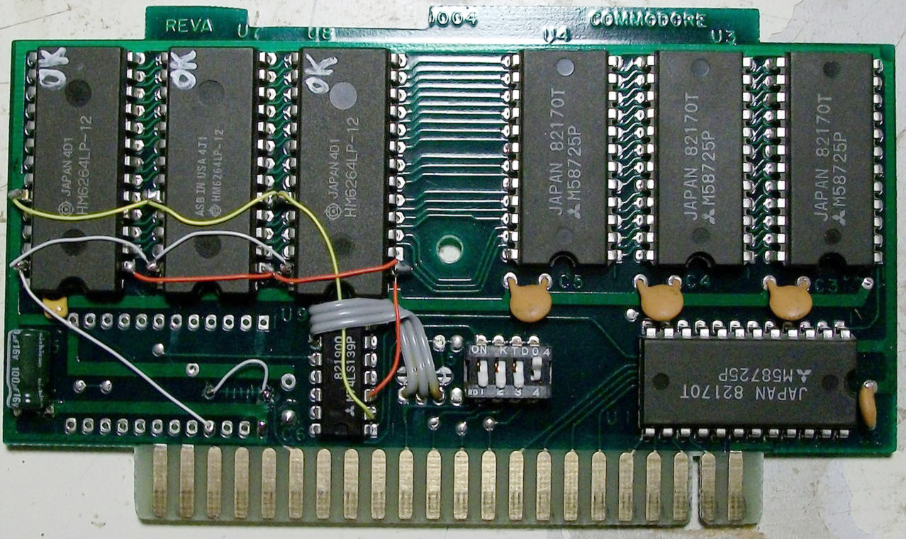
If I may impose once again, my interpretation of your instructions is below, with red indicating the traces to cut, and the green indicating hookup wires to add. And I forgot to mention that I did put a 100nF cap in the indicated place. Is this correct for SRAM, too?
VIC-20 Projects: wAx Assembler, TRBo: Turtle RescueBot, Helix Colony, Sub Med, Trolley Problem, Dungeon of Dance, ZEPTOPOLIS, MIDI KERNAL, The Archivist, Ed for Prophet-5
WIP: MIDIcast BASIC extension
he/him/his
WIP: MIDIcast BASIC extension
he/him/his
-
Mike
- Herr VC
- Posts: 4841
- Joined: Wed Dec 01, 2004 1:57 pm
- Location: Munich, Germany
- Occupation: electrical engineer
Re: Repurposing a Super Expander (or 3K RAM)
The indicated positions of the cuts are (also) correct, but only feasible to do as long as the SRAM chip was not already fitted. With the chip (still) fitted, you'd apply the cuts on the traces between the RAM and the ROM.chysn wrote:[...] my interpretation of your instructions is below, with red indicating the traces to cut, [...]
They're fine, yes. And best hidden on the soldering side.[...] and the green indicating hookup wires to add.
Those capacitors generally stabilize the supply voltage of those chips, which is very important once the chips (need to) operate at frequencies of 1 MHz or more (which is the case here). You find those little guys literally strewn across the VIC-20 mainboard.And I forgot to mention that I did put a 100nF cap in the indicated place. Is this correct for SRAM, too?
-
chysn
- Vic 20 Scientist
- Posts: 1205
- Joined: Tue Oct 22, 2019 12:36 pm
- Website: http://www.beigemaze.com
- Location: Michigan, USA
- Occupation: Software Dev Manager
Re: Repurposing a Super Expander (or 3K RAM)
Thanks for confirming! Yes, all the hookups will be on the other side, and the SRAM chip is currently off the board.
VIC-20 Projects: wAx Assembler, TRBo: Turtle RescueBot, Helix Colony, Sub Med, Trolley Problem, Dungeon of Dance, ZEPTOPOLIS, MIDI KERNAL, The Archivist, Ed for Prophet-5
WIP: MIDIcast BASIC extension
he/him/his
WIP: MIDIcast BASIC extension
he/him/his
-
chysn
- Vic 20 Scientist
- Posts: 1205
- Joined: Tue Oct 22, 2019 12:36 pm
- Website: http://www.beigemaze.com
- Location: Michigan, USA
- Occupation: Software Dev Manager
Re: Repurposing a Super Expander (or 3K RAM)
But seriously, I can't wait until I have another day off to try something this cool. Here it is, working as expected:
I also tried fill operations from $A000 to $A7FF, and all the RAM is usable. As you suggested it would, the RAM does repeat every 2K, but I'm fine with that.
Thanks again!
Thanks again!
- Attachments
-
-
VIC-20 Projects: wAx Assembler, TRBo: Turtle RescueBot, Helix Colony, Sub Med, Trolley Problem, Dungeon of Dance, ZEPTOPOLIS, MIDI KERNAL, The Archivist, Ed for Prophet-5
WIP: MIDIcast BASIC extension
he/him/his
WIP: MIDIcast BASIC extension
he/him/his
-
eslapion

- ultimate expander
- Posts: 5458
- Joined: Fri Jun 23, 2006 7:50 pm
- Location: Canada
- Occupation: 8bit addict
Re: Repurposing a Super Expander (or 3K RAM)
I suggest you take a look at this:
Both the VIC-1110 8k and VIC-1111 16k RAM expansions use the same PCB. However, on the VIC-1110, 4 2k x8 SRAM footprints are left empty. On one of these boards, I filled 3 of the empty footprints with 8k x8 SRAM ICs and networked the missing extra address lines accordingly. This turns the 8k RAM expansion into a 32k RAM expansion.
There is also a small white jumper wire which allows you to make the expansion 'read-only' for full compatibility with cartridge images.
Be normal.