I was thinking about my guess about the square wave being gated with noise... this might also explain why the result doesn't sound like pure white noise but instead it's somewhat .... "soundy" (can't find the right word, but if you have ever heard a VIC 20 you know what I talking about).
Another important thing to discover is when the LFSR is advanced: at every clock cycle, or only when the voice is enabled?
I'll try to write down some code implementing your findings, I'll either hack the JavaScript emulator or write it directly for the FPGA (I have a Mistica FPGA board).
6561 Die Shot Reversing Explorations
Moderator: Moderators
-
lance.ewing
- Vic 20 Afficionado
- Posts: 413
- Joined: Sat Nov 10, 2012 3:19 pm
- Website: https://sites.google.com/site/mos6561vic/
Re: 6561 Die Shot Reversing Explorations
Having re-checked the diagram of the 7-bit counter from that older topic from 2016, it is mostly correct. The only thing I noticed that was missing was a link between the reload line and the AND gate in the lower left corner. Its quite obvious in the original diagram from the older thread that that AND gate was missing one of its inputs. I've corrected this in the image below:lance.ewing wrote:I'm going to look over that section of the die shot again to confirm this, but at the moment I think we can say that part of the bottom half of the pink box is the 7 bit counter.
Re: 6561 Die Shot Reversing Explorations
so if get it right the big NOR does an equality check to 127 ? In other words this would be equivalent to:
Code: Select all
IF reg = 127 THEN reg = loadvalue ELSE reg = reg + 1-
lance.ewing
- Vic 20 Afficionado
- Posts: 413
- Joined: Sat Nov 10, 2012 3:19 pm
- Website: https://sites.google.com/site/mos6561vic/
Re: 6561 Die Shot Reversing Explorations
Yeah, I think so. It might not be obvious from the diagram, but the signal value going to the NOR gate from each bit is the inverse value. So when the counter is 127, then each of those inputs to the NOR gate is LOW, so the output of the NOR is HIGH.
It appears that the output of the NOR also goes towards the 16-bit LFSR, to the logic that controls the shifting within the LFSR. I'm still trying to work out exactly how that logic works. I think I've reversed the gates, but it isn't behaving as I'd expect when I try to simulate it, so I'm not convinced I have it correct yet. I'm going to re-examine that part of the die shot to see what I'm missing.
I haven't started looking at the area that you suspect is the 8-bit shift register, so not yet able to comment on that, but I'm guessing that you're probably right about that area being where it is. It certainly looks like there are 8 similar structures in there.
Re: 6561 Die Shot Reversing Explorations
Some other random remarks that might help:
- there should be a clock divider common to all four voices which provides a div64, div32, div16 and div32(?) signal to frequency counters of CR-A, CR-B, CR-C and CR-D. The factor for CR-D is not known exactly, but it's guessed to be 32 (in which case the signal would be shared with CR-B).
- the 16 bit LFSR needs an initial seed because a zero value would lock the LFSR always on the same value. But since it only needs to be <>0, it might be that just one bit is set, perhaps via the LFSR "shift and feedback" on the bit 0. But of course it might be there is a value loaded in the traditional way, in which case we would like to know when this happens (at reset or at voice enabled).
- the 8 bit LFSRs for generating the square wave: why are they there at all? Square waves and noise gating could have been implemented with simple flip-flops, so I wonder why they chose to implement them. My hope is that there is an undocumented way to load values directly on these LFSRs (that would explain their existance). Currently only some limited values can be loaded with the trick discovered by Viznut and Pwp.
Re: 6561 Die Shot Reversing Explorations
I implemented the noise generator in my FPGA board and it sounds very close to the original. Still not the same, but that might be due the different filter that makes the sound assume a different "color".
The clock divider for the noise generator I mentioned in my previous post seems to be 64, so if I right it should be in common with CR-A. I evaluated it by "ear". 32 seems a bit high pitched and 128 is definitely too low.
The clock divider for the noise generator I mentioned in my previous post seems to be 64, so if I right it should be in common with CR-A. I evaluated it by "ear". 32 seems a bit high pitched and 128 is definitely too low.
Re: 6561 Die Shot Reversing Explorations
A small update: I figured out that the noise out of the LFSR is not in AND with the square wave, but it's XOR (it makes a lot more sense, but I figured it only now). So its appropriate clock divider now seems to be 32. But there's still something missing, as it doesn't sound like the real VIC-20 yet.
BTW, do we have some clue about the VOLUME of the noise voice? It seems to me that it's not in the same ratio as the other voices (e.g 1/4) but it's half than the sound voices. Which makes sense if you want music and sound fx to coexist.
BTW, do we have some clue about the VOLUME of the noise voice? It seems to me that it's not in the same ratio as the other voices (e.g 1/4) but it's half than the sound voices. Which makes sense if you want music and sound fx to coexist.
-
lance.ewing
- Vic 20 Afficionado
- Posts: 413
- Joined: Sat Nov 10, 2012 3:19 pm
- Website: https://sites.google.com/site/mos6561vic/
Re: 6561 Die Shot Reversing Explorations
I am able to answer a few of your questions. Hopefully I'll get a chance to go into the details over the weekend. For now I thought I'd mention that the output of the 16-bit LFSR, i.e. from the first bit, then directly controls the shifting of the 8-bit square wave shift register. What I mean is that a HIGH signal coming out of the LFSR causes the 8-bit SR to shift by one. More details to follow soon.
-
lance.ewing
- Vic 20 Afficionado
- Posts: 413
- Joined: Sat Nov 10, 2012 3:19 pm
- Website: https://sites.google.com/site/mos6561vic/
Re: 6561 Die Shot Reversing Explorations
Another update from me that I feel I should pass on immediately. It appears I made a mistake in my earlier posts about the LFSR. It isn't using an XOR but is instead using an XNOR. I will retrospectively correct that post soon, and will put an Update note at the bottom of it to say that I've done that correction. For now I wanted to share in this new post the actual implementation of the XNOR at the silicon level:
I initially thought that this represented an XOR, but the bit to the right is actually an XNOR, in fact exactly that right hand part is shown on the wikipedia page for XNOR as a possible XNOR circuit:
https://en.wikipedia.org/wiki/XNOR_gate
And the two identical circuits on the left hand side are one possible way of constructing a 2-input XOR circuit, as seen in figure 5c on the following page:
http://pastraiser.com/technology/nmos/b ... gates.html
and that 2-input structure that appears twice on the left hand side when in isolation certainly behaves as an XOR when simulated in logisim. And I've tested the right hand side in isolation and confirmed it behaves as an XNOR.
So the equivalent of the above circuit is actually the following:
Sorry for putting you wrong in the earlier post. What it means is that that diagram I found online for a 16-bit LFSR isn't a match for the 6561. The taps are a match, but the rightmost XOR in that diagram needs to be an XNOR (which I guess makes the whole thing a 4-input XNOR?)
I think this might hold the secret to the seeding question as well, because the simulations I was doing for the full 16-bit LFSR were not solving the issue of seeding while I thought that this was an XOR. Now that I realise its an XNOR, it means that the NAND gate that takes the output of the XNOR and the value of the 8th bit of CR-D (voice enable) as its two inputs will now feed a LOW into the LFSR from the start, regardless of whether every bit in the shift register is HIGH or LOW. My simulation is now working as it should. The whole SR can be cleared out while the noise voice is turned off. Actually what happens when the noise voice is turned off is that every bit in the LFSR gets set to a HIGH value after 16 shifts, since it shifts HIGH in from the top while the noise voice is turned off. Then as soon as the noise voice is turned on, it begins shifting LOWs in, then when it starts hitting the tap points, it starts changing from HIGH to LOW depending on the random sequence (i.e. output of that XNOR).
I will post a diagram of the full LFSR circuit tomorrow. For now I'm off to bed.
- noise_reg_lfsr_xnor_actual.png (4.45 KiB) Viewed 5891 times
https://en.wikipedia.org/wiki/XNOR_gate
And the two identical circuits on the left hand side are one possible way of constructing a 2-input XOR circuit, as seen in figure 5c on the following page:
http://pastraiser.com/technology/nmos/b ... gates.html
and that 2-input structure that appears twice on the left hand side when in isolation certainly behaves as an XOR when simulated in logisim. And I've tested the right hand side in isolation and confirmed it behaves as an XNOR.
So the equivalent of the above circuit is actually the following:
- noise_reg_lfsr_xnor_equiv.png (2.07 KiB) Viewed 5891 times
I think this might hold the secret to the seeding question as well, because the simulations I was doing for the full 16-bit LFSR were not solving the issue of seeding while I thought that this was an XOR. Now that I realise its an XNOR, it means that the NAND gate that takes the output of the XNOR and the value of the 8th bit of CR-D (voice enable) as its two inputs will now feed a LOW into the LFSR from the start, regardless of whether every bit in the shift register is HIGH or LOW. My simulation is now working as it should. The whole SR can be cleared out while the noise voice is turned off. Actually what happens when the noise voice is turned off is that every bit in the LFSR gets set to a HIGH value after 16 shifts, since it shifts HIGH in from the top while the noise voice is turned off. Then as soon as the noise voice is turned on, it begins shifting LOWs in, then when it starts hitting the tap points, it starts changing from HIGH to LOW depending on the random sequence (i.e. output of that XNOR).
I will post a diagram of the full LFSR circuit tomorrow. For now I'm off to bed.
-
lance.ewing
- Vic 20 Afficionado
- Posts: 413
- Joined: Sat Nov 10, 2012 3:19 pm
- Website: https://sites.google.com/site/mos6561vic/
Re: 6561 Die Shot Reversing Explorations
Without further ado, here is the full circuit diagram for the 16-bit LFSR, including the feedback and shifting logic:
Obviously you will have to click on that, and then zoom in to see the full sized image. Once you've done that, you'll notice the feedback XNOR circuit that I was discussing in my previous post. In the top left corner, we have CR-D-7' which is the inverse of the 8th bit of CR-D (the noise reg enable bit). It then goes through an inverter with the signal on the other side being CR-D-7. I've included this inverter in the diagram because it is there in this part of the die shot, and it makes it clear that the signal coming into this part of the die shot is the inverse of the noise voice enable bit.
In the middle of the diagram, and taking up most of it, are the 16 bits of the LFSR. Each bit is made up of three pass transistors, and two inverters. The design is more or less a standard dynamic shift register design. I was a bit puzzled by the third pass transistor at first, which is the one controlled by the middle control line, but then I realised it is probably for refreshing the level. I managed to simulate this fully in Logisim, in fact the diagram above is an export of the Logisim circuit I was simulating. I have added labels for each of the current LFSR bit levels. These are the points that are tapped and also where the output is, so it must represent the current level of the bits.
As mentioned in one of my earlier posts, I've used a naming convention on those bit labels of NSR for Noise Shift Register and started the numbering at 0. This is pretty standard for labelling the bits of something like this, i.e. bit 0 being the first bit. This is done throughout the 6561 datasheet for example and is what I've done in all my diagrams to date. I wanted to reiterate this though so that it is clear what bits are used as taps. NSR3 isn't, for example, the 3rd bit but is instead the 4th bit.
Looking now at the bottom of the diagram, we have the shifting logic. Coming into this we have a signal called CNT_RELOAD. This is the same signal that reloads the 7-bit counter. The net effect of this shifting logic is that whenever the 7-bit counter reloads, the LFSR shifts down by one bit (down in relation to the diagram). This answers one of nippur72's earlier questions, which was regarding how often the LFSR shifts. So the answer is by one bit every reload of the counter.
Although that shifting logic looks a bit involved, what it does is generate three different shift signals that connect to the three different pass transistors in each bit of the LFSR. These shift signals are generated using a combination of the CNT_RELOAD signal and the two clocks, F1 and F2. While CNT_RELOAD is LOW, the shift register doesn't shift at all, but when CNT_RELOAD goes HIGH, the three signals start doing there thing. I could produce a timing diagram for it if someone was interested, but for the purposes of emulation, I think you mainly just need to advance the LFSR by one bit when the counter reloads (and obviously do the feedback as well). You might recognise within this shifting logic that there is an SR flip flop. It seems then that two of the shift signals are mutually exclusive and in fact they control the two main pass transistors and would therefore be the two phases of a single bit shift.
The LFSR shifts whenever the CNT_RELOAD signal goes HIGH. Shifting doesn't appear to be affected by the noise voice enable bit. Obviously though the feedback logic is affected by the noise voice enable bit. So when the noise voice is disabled, it continues shifting and shifts HIGH in at the top. After 16 counter reloads, every bit will be HIGH. It will continue to shift after this, but obviously shifting HIGH into something that already has HIGH in every bit isn't going to make a difference at that point.
As previously mentioned, NSR0 is the output bit for the LFSR.
-
lance.ewing
- Vic 20 Afficionado
- Posts: 413
- Joined: Sat Nov 10, 2012 3:19 pm
- Website: https://sites.google.com/site/mos6561vic/
Re: 6561 Die Shot Reversing Explorations
Another update to say that the 8th input to the big NOR gate labelled UNKNOWN in the following diagram of the 7-bit counter... :
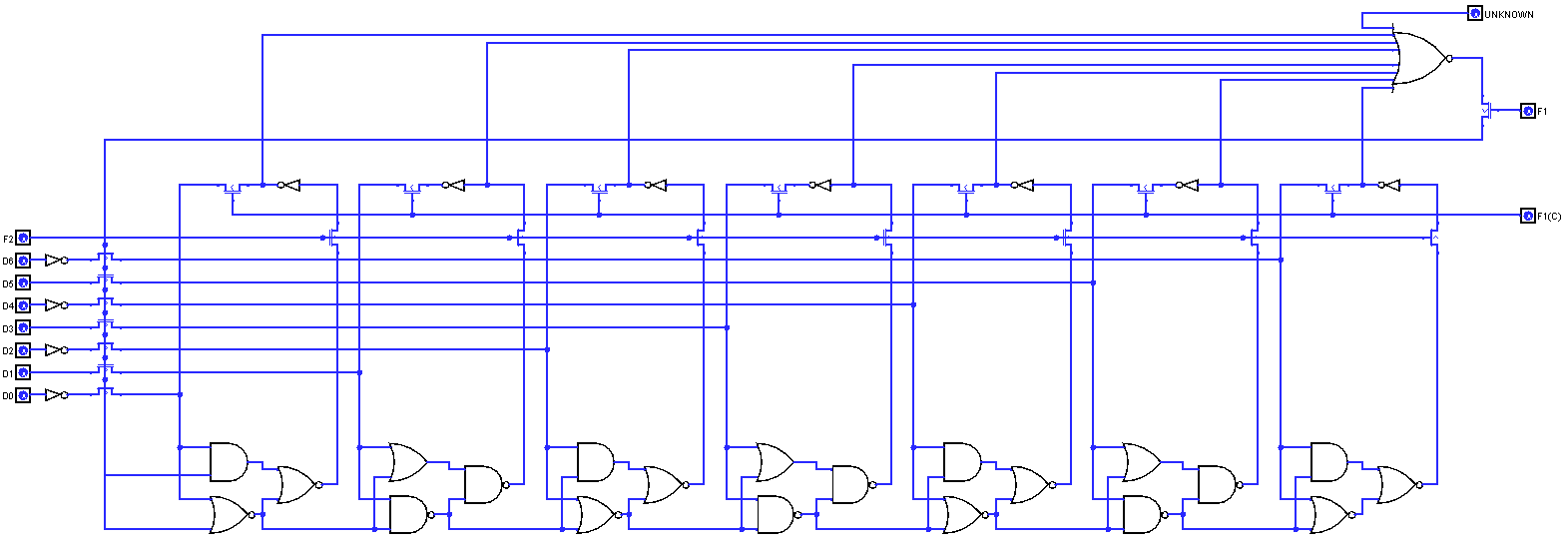
...is also the signal that controls how often the 7-bit counter increments. I think it must go back up to where the clock dividers are (which incidentally is not within the pink boxes but appears to be in an area above them and to the left of the POT comparators). I haven't yet fully reversed the increment logic for the 7-bit counter, but the inputs into it are F1, F2, and this same signal that is the 8th input to the big "reload counter" NOR. Tracing it back, it comes into the pink box from that area above already mentioned.
Without having reversed the clock dividers yet (which might take some time, and is probably going to be after I've finished with the pink box), my best guess at this point is that the output of the relevant clock divider is what controls the rate that the counter increments. We'll get there eventually though.
I think the next area I'm going to reverse and show diagrams for is the 8-bit square wave shift register. I can already see it and how it works, and it matches what people have deduced from observation and experimentation, but it will be nice to show the circuit diagrams to confirm it visually.
-
lance.ewing
- Vic 20 Afficionado
- Posts: 413
- Joined: Sat Nov 10, 2012 3:19 pm
- Website: https://sites.google.com/site/mos6561vic/
Re: 6561 Die Shot Reversing Explorations
The topic of this post is the 8-bit shift register.
If you click on it, you'll get a closer image and be able to better see the coloured boxes I refer to. The yellow box is where the 8-bit shift register lives, the light pink box is where the 7-bit counter lives, the orange box is the increment logic for the counter, and beside it the light blue box contains the shift logic for the 8-bit shift register. The red box is the 16-bit shift register, and above that in a purple box is the feedback logic for the 16-bit shift register, and below the red box in a dark blue box is the shift logic for the 16-bit shift register. Unidentified at this point of time is what is in the black box, but it does something with all 8 bits of the 8-bit shift register and involves several resistors. Maybe its the start of the DAC part of the circuit. It has an output that appears to mix with the outputs of the other three voices, but we'll leave that black box for another post.
Let's start by looking at an even closer up image of the 8-bit shift register:
Open that image in another tab and you'll be able to see the labels that I've put on to the various contacts, and a few arrows that attempt to show how things work.
This is my logisim diagram for the 8-bit shift register:
Once again you'll have to click on that image, or open it in another tab, to see the detail.
A few things to note about this:
But as has been observed in the past, if the noise voice enable bit is turned on and off, it is possible to change this pattern of HIGHs and LOWS. I was able to, for example, set up a pattern of HIGH, LOW, HIGH, LOW, HIGH, LOW, HIGH, LOW across the 8 bits by simulating this voice enable switching in Logisim.
Back to the question about how it combines the output of the 16-bit LFSR and output of the 8-bit shift register. I think the above answers it. As already mentioned in earlier posts, there is a single output from the 16-bit LFSR (it's first bit) and that controls the shifting of the 8-bit shift register. The "output" of the 8-bit shift register appears to be all 8 bits. What exactly it does with them is in the black box in the first diagram of this post. This will probably be the next area of the die shot that I'm going to spend time reversing.
I can now confirm that that part of the pink box is indeed the 8-bit shift register. I've included an image below that shows a close up of the noise voice section of the die shot with various different coloured boxes placed on top of it:nippur72 wrote: Looking at the pink boxes I think I can see the 8-bit shift register used to generate the square waves (it should be the horizontal thing just above the middle of the box). Well, if that is the case, it means an important thing: such 8-bit LFSR is also present in the noise generator (pink boxes are almost identical to my eyes).
The answer to this question is that no, it doesn't NAND or NOR the two shift register outputs together. Instead the output of the 16-bit LFSR directly triggers a shift of the 8-bit SR. The rest of this post will go into the detail of this.nippur72 wrote:Now my guess is that the output of this 8-bit LFSR goes NAND with the 16-LFSR. This would form a sort of "noisy square wave"? Just my guess, I don't know if that makes sense.
Let's start by looking at an even closer up image of the 8-bit shift register:
This is my logisim diagram for the 8-bit shift register:
A few things to note about this:
- The input to the shifting logic is the NSR0 signal from the 16-bit LFSR, i.e. the output of the 16-bit LFSR, which is it's first bit.
- The design of the 8-bit shift register is internally the same as that of the 16-bit LFSR, except that it is obviously 8 bits.
- The shift logic for the 8-bit register is also the same, except that the input is NSR0 rather than the counter reload signal.
- It also has the three different shift signals for controlling a shift, which I've given labels this time as SHIFT PH1 (shift phase 1), SHIFT PH2 (shift phase 2), and SR_REFRESH (shift register refresh).
But as has been observed in the past, if the noise voice enable bit is turned on and off, it is possible to change this pattern of HIGHs and LOWS. I was able to, for example, set up a pattern of HIGH, LOW, HIGH, LOW, HIGH, LOW, HIGH, LOW across the 8 bits by simulating this voice enable switching in Logisim.
Back to the question about how it combines the output of the 16-bit LFSR and output of the 8-bit shift register. I think the above answers it. As already mentioned in earlier posts, there is a single output from the 16-bit LFSR (it's first bit) and that controls the shifting of the 8-bit shift register. The "output" of the 8-bit shift register appears to be all 8 bits. What exactly it does with them is in the black box in the first diagram of this post. This will probably be the next area of the die shot that I'm going to spend time reversing.
Re: 6561 Die Shot Reversing Explorations
HYPEE !! HURRAH!!! 
I think we got it!!! (Actually YOU got it )
)
I just implemented in FPGA what you explained in your last posts, in particular the XNOR gating and the NAND that feeds the 8-LFSR. At first it didn't sound right, the repeating pattern I was hearing for POKE 36877,254 on the FPGA was the same as "253" on the real VIC. And "253" on the FPGA was "251" on the VIC. That was strange. I thought it was the 16-LFSR advancing too slowly, but then it dawned on me that it could be the clock divider.
Indeed it was! setting it to 8 instead of 16, MAKES IT SOUND EXACTLY LIKE A VIC 20 ! Yeee!
So now we have the noise generator completely reverse engineered! (at least for emulation/reimplementation purposes).
A big thank you Lance, your work was incredible!
Here is the small piece of VHDL that implements it:
- audio_div_8 is the clock divider
- noise_sg_cnt is the frequency counter
- noise_LFSR(15 downto 0) is the 16 bit shift register
- noise_sg_sreg(7 downto 0) is the 8 bit shift register
- r_noise_enabled is the "enable" bit
- noise_sg is the final output
line 3 is counter reload
line 5 is 8-bit shift register shift
line 7 is LFSR shift
line 8 is LSFR feedback (notice the XNOR and NAND)
line 10 is frequency counter increment
P.S. Looking at the clock dividers (64, 32, 16,  makes me think that the original project was to provide 4 sound voices, then maybe they sacrificed the last one either because too high pitched or just to provide noise fx for games.
I think we got it!!! (Actually YOU got it
I just implemented in FPGA what you explained in your last posts, in particular the XNOR gating and the NAND that feeds the 8-LFSR. At first it didn't sound right, the repeating pattern I was hearing for POKE 36877,254 on the FPGA was the same as "253" on the real VIC. And "253" on the FPGA was "251" on the VIC. That was strange. I thought it was the 16-LFSR advancing too slowly, but then it dawned on me that it could be the clock divider.
Indeed it was! setting it to 8 instead of 16, MAKES IT SOUND EXACTLY LIKE A VIC 20 ! Yeee!
So now we have the noise generator completely reverse engineered! (at least for emulation/reimplementation purposes).
A big thank you Lance, your work was incredible!
Here is the small piece of VHDL that implements it:
- audio_div_8 is the clock divider
- noise_sg_cnt is the frequency counter
- noise_LFSR(15 downto 0) is the 16 bit shift register
- noise_sg_sreg(7 downto 0) is the 8 bit shift register
- r_noise_enabled is the "enable" bit
- noise_sg is the final output
line 3 is counter reload
line 5 is 8-bit shift register shift
line 7 is LFSR shift
line 8 is LSFR feedback (notice the XNOR and NAND)
line 10 is frequency counter increment
Code: Select all
if audio_div_8 then
  if noise_sg_cnt = "1111111" then
    noise_sg_cnt <= r_noise_freq + "1";
    if noise_LFSR(0)='1' then
      noise_sg_sreg <= noise_sg_sreg(6 downto 0) & (not noise_sg_sreg(7) and r_noise_enabled);
    end if;
    noise_LFSR(15 downto 1) <= noise_LFSR(14 downto 0);
    noise_LFSR(0)           <= ((noise_LFSR(3) xor noise_LFSR(12)) xnor (noise_LFSR(14) xor noise_LFSR(15))) nand r_noise_enabled;
  else
    noise_sg_cnt <= noise_sg_cnt + "1";
  end if;
end if;
noise_sg <= noise_sg_sreg(0);
-
lance.ewing
- Vic 20 Afficionado
- Posts: 413
- Joined: Sat Nov 10, 2012 3:19 pm
- Website: https://sites.google.com/site/mos6561vic/
Re: 6561 Die Shot Reversing Explorations
That is great to hear!!nippur72 wrote: setting it to 8 instead of 16, MAKES IT SOUND EXACTLY LIKE A VIC 20 ! Yeee!
So now we have the noise generator completely reverse engineered! (at least for emulation/reimplementation purposes).
Yeah, it wouldn't surprise me. I'm quite keen now to look at the design of one of the other voices to see how much they differ. I assume the 7-bit counter in those voices has the counter reload signal linking directly to the input of the shift logic for their 8-bit shift register. If that's the only difference then they are very similar. The noise bit seems like something literally just tagged on to the side.nippur72 wrote: P.S. Looking at the clock dividers (64, 32, 16, 8 ) makes me think that the original project was to provide 4 sound voices, then maybe they sacrificed the last one either because too high pitched or just to provide noise fx for games.
-
lance.ewing
- Vic 20 Afficionado
- Posts: 413
- Joined: Sat Nov 10, 2012 3:19 pm
- Website: https://sites.google.com/site/mos6561vic/
Re: 6561 Die Shot Reversing Explorations
Well this is interesting. Although that area within the black box takes all 8 bits of the shift register, as far as I can tell, the only one that affects the output is the first bit. The other seven bits are connected up into a network with each other involving resistors and transistors, but none of it is connected to the output, and I can see at least two bits of polysilicon that appear to be completely redundant, i.e. they don't connect to anything, which makes me think that parts of this circuit within the black box (maybe most of it) has been deliberately disconnected. And this is not just the case with the noise voice. The same is true of all four voices. So that black box area is mostly redundant as far as I can. Maybe it was something experimental.lance.ewing wrote:Unidentified at this point of time is what is in the black box, but it does something with all 8 bits of the 8-bit shift register and involves several resistors. Maybe its the start of the DAC part of the circuit. It has an output that appears to mix with the outputs of the other three voices, but we'll leave that black box for another post.