Page 5 of 6
Re: S-Video conversion possible as plug-and-play solution?
Posted: Mon Jul 25, 2016 7:20 pm
by RobertBe
I wrote:Ray says it's a "very early E version."
At yesterday's FCUG meeting, we opened up the machine to look at Ray's handiwork. The sticker on cage around the power transistor says, "7/81."
Prepping for CommVEx,
Robert Bernardo
Fresno Commodore User Group
http://www.dickestel.com/fcug.htm
July 30-31 Commodore Vegas Expo v12 -
http://www.portcommodore.com/commvex
Re: S-Video conversion possible as plug-and-play solution?
Posted: Sun Nov 06, 2016 8:08 pm
by oracle_jedi
Hey guys,
Can someone explain Oge's comment to me:
You could try amplifying the Chroma and then 0,1uF/1uF bipolar capacitor plus 470/1000 Ohm resistor between VIC and TV in order to protect the VIC itself. And a 75 Ohm (Chroma to GND) resistor as a final touch.
I've followed the practice described by Bear of a 0.1uF capacitor off Pin 2, followed by a 75 Ohm resistor to Pin 5 for Chroma. So far it has worked well. But this comment has me concerned I am stressing the VIC chip.
I've seen several suggestions of larger resistors. 360 Ohm has been suggested as a better option than the 75. But is the suggestion here that an additional resistor be added than connects the chroma line to a local GND on the VIC's motherboard via a 75 Ohm resistor too? I'm not sure what is being advised here.
I'd like to see the above comment drawn as a schematic if anyone has one.
Thanks!
Re: S-Video conversion possible as plug-and-play solution?
Posted: Sun Nov 06, 2016 9:14 pm
by eslapion
oracle_jedi wrote:Hey guys,
Can someone explain Oge's comment to me:
You could try amplifying the Chroma and then 0,1uF/1uF bipolar capacitor plus 470/1000 Ohm resistor between VIC and TV in order to protect the VIC itself. And a 75 Ohm (Chroma to GND) resistor as a final touch.
I've followed the practice described by Bear of a 0.1uF capacitor off Pin 2, followed by a 75 Ohm resistor to Pin 5 for Chroma. So far it has worked well. But this comment has me concerned I am stressing the VIC chip.
I've seen several suggestions of larger resistors. 360 Ohm has been suggested as a better option than the 75. But is the suggestion here that an additional resistor be added than connects the chroma line to a local GND on the VIC's motherboard via a 75 Ohm resistor too? I'm not sure what is being advised here.
I'd like to see the above comment drawn as a schematic if anyone has one.
Thanks!
In theory, a device which generates composite video or S-Video signal should have an output impedance of 75 Ohms. In practice, this would result in the amplitude of the chroma signal coming out of your VIC-20 having an excessive amplitude relative to RS-170A specifications.
A 75 Ohms resistor will provide a signal that's adequate if you use a Commodore monitor with separate luma/chroma RCA jacks. This system was a precursor to real S-Video with 4 pin mini DIN jack and had slightly different electrical specs.
If you want to reduce the amplitude of the chroma to acceptable S-Video specs, use a 360 Ohms resistor. This resistor will interact with the 75 Ohms input impedance of the display device and act as a voltage divider.
There are a few TV sets which have a higher input impedance (up to 1k Ohms) and they may require a higher resistor value.
IMHO, a correct way to protect this new output would be to use a pair of diodes the same way as on the IEC port on the C64c.
Re: S-Video conversion possible as plug-and-play solution?
Posted: Sun Jan 08, 2017 5:40 am
by Kakemoms
I just bought a USB Audio/Video grabber in the local store (type ArcSoft). It has S-Video input and composite, so I settled for the S-Video with mrr19121970's modified chroma/luma output.. and.. nothing. I also tested composite input and nothing from that either.
I get a nice picture on my 1084. I also get a nice picture from the Video grabber with my Blueray player, so it seems like the video signal is the problem.
I also tried to add an additional resistor on the chroma out pin (between the chroma wire and the wire on the cable), but it didn't help either.
Suggestions?
Re: S-Video conversion possible as plug-and-play solution?
Posted: Sun Jan 08, 2017 5:45 am
by Boray
You could try to adjust those pots inside the vic to get a stronger signal.
Re: S-Video conversion possible as plug-and-play solution?
Posted: Sun Jan 08, 2017 8:28 am
by Kakemoms
Tried it already with no success.. Even the luma alone didn't lock.
I've had the same problem with video to VGA converters.. I can get a picture on my TV with video from the VIC-20, but nothing through the converter. My Amiga 1200 looks excellent through the same converter, so it may be related to the poor specs of the Video signal.
My picoscope shows this as a p-p collection. In DC it reports it as being from 1.8V to 2.4V above ground(!!) I am thinking recapping might be wise.. Is this normal for the S-Video mod?
P-P diagram of LUMA:
Edit: Oh, maybe I need to terminate it..

--> Nope, no difference there. Even with the 1084 connected and showing a nice picture, the signal is still above 2 Volts.
Re: S-Video conversion possible as plug-and-play solution?
Posted: Sun Jan 08, 2017 9:14 am
by Mike
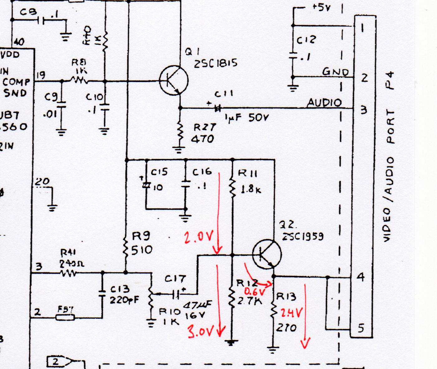
Kakemoms wrote:In DC it reports it as being from 1.8V to 2.4V above ground(!!)
A sharp look at the schematics and working out the setpoint voltages helps a lot here:
Re: S-Video conversion possible as plug-and-play solution?
Posted: Sun Jan 08, 2017 1:46 pm
by eslapion
Kakemoms wrote:My picoscope shows this as a p-p collection. In DC it reports it as being from 1.8V to 2.4V above ground(!!) I am thinking recapping might be wise.. Is this normal for the S-Video mod?
P-P diagram of LUMA:
LUMA.png
Edit: Oh, maybe I need to terminate it..
--> Nope, no difference there. Even with the 1084 connected and showing a nice picture, the signal is still above 2 Volts.
Above 2 volts is EXACTLY AS IT SHOULD BE! This is an AC signal and therefore it must have a positive DC offset to be valid and suffer no clipping. Since the VIC-I operates on 0-5Vdc, you should expect a DC offset close to 2-3 volts.
The graphic you posted shows the signal going from -0.4 to +0.2 and this gives it an AMPLITUDE of 0.6V p-p (peak to peak) which is 60% of the right amplitude. Turn the pot (R10) to increase the amplitude until you get 1V p-p. DON'T TOUCH the variable capacitor.
Re: S-Video conversion possible as plug-and-play solution?
Posted: Wed Jan 11, 2017 6:44 am
by Kakemoms
Short update:
Changing pot value didn't help and I gave up on the video grabber. Anyone else had luck with grabbing the vic video signal into a PC?
Re: S-Video conversion possible as plug-and-play solution?
Posted: Wed Jan 11, 2017 9:51 am
by eslapion
Kakemoms wrote:Short update:
Changing pot value didn't help and I gave up on the video grabber. Anyone else had luck with grabbing the vic video signal into a PC?
The video signal of the VIC-20 is not exactly standard. If you adjusted the signal so it's amplitude is 1V p-p and your video grabber doesn't accept it then the only way for this grabber to accept it is to use a time base corrector - an expensive device which was mostly necessary with sophisticated devices like the Amiga Video Toaster.
In the past, I have owned a Digital Video Creator (the very 1st one for parallel port) and a DVDXpress DX2. Both supported the VIC-20's signal IF and only IF it was correctly adjusted.
The funny thing is, when it is set properly, the DVC can act as a time base corrector!!
Re: S-Video conversion possible as plug-and-play solution?
Posted: Sun Jan 15, 2017 12:57 pm
by ral-clan
Just adding that Time Base Correctors for old analog video are probably a lot cheaper now that almost everyone has moved onto digital video editing, so there may be some deals on eBay.
Also, some old MiniDV camcorders could accept an external analog video signal, and pass this through to their firewire output (which can be fed to a PC equipped with a Firewire port). In doing so, some of these cameras would act as a time-base corrector.
MiniDV cameras are pretty cheap right now on eBay, and for this purpose you wouldn't even need one with a working tape transport, it would just need to be electrically functional (even cheaper).
Re: S-Video conversion possible as plug-and-play solution?
Posted: Sun Jan 15, 2017 4:38 pm
by Mike
Since at least two people here seemed to miss the broad hint:
Mike wrote:Kakemoms wrote:In DC it reports it as being from 1.8V to 2.4V above ground(!!)
A sharp look at the schematics and working out the setpoint voltages helps a lot here: [...]
The video out of the VIC-20 *has* that DC component, *by design* of the output amplifier stage - and obviously older equipment, like a 1084 monitor, tolerates it. Doesn't mean *all* equipment is able to do that. If fed directly into an amplifier of a low-voltage design, this bias voltage can easily drive the input stage into saturation. One obvious solution would be to put a decoupling capacitor into the video signal. I'd try out this at first before resorting to much more expensive devices:
The decoupling capacitor has to pass at least the 50 Hz component of the video retrace (with PAL, 60 Hz for NTSC), and it forms a high pass with the 270 Ohm resistor in the VIC-20, and the 75 Ohm impedance of a standard AV input in parallel. Q2 is (mostly) a current source and so acts as open in the small signal domain.
Code: Select all
             1
50 Hz = -----------
        2pi * R * C
with R = 270 Ohm || 75 Ohm ~= 60 Ohm. => C ~= 54 µF
An 100 µF electrolytic capacitor (used with the + side oriented to the VIC-20) should be a commodity in a hobbyist's toolbox.

Re: S-Video conversion possible as plug-and-play solution?
Posted: Tue Jan 17, 2017 11:13 pm
by rmelick
mrr19121970 wrote:I did another machine. This time I used 360 ohm and not 75 ohm like before.
Hello, I did your mod today and I love it!! I have a cheap, old LCD TV that looks as bad as the photo of particularly bad composite on:
http://sleepingelephant.com/denial/wiki ... deo_output I was trying to smooth things out as best I could with the contrast and focus.
After following your directions today my picture is now flawless and perfect. Thank you for posting!!
Re: S-Video conversion possible as plug-and-play solution?
Posted: Fri Jan 20, 2017 11:45 am
by Kakemoms
Mike wrote:
The video out of the VIC-20 *has* that DC component, *by design* of the output amplifier stage - and obviously older equipment, like a 1084 monitor, tolerates it. Doesn't mean *all* equipment is able to do that. If fed directly into an amplifier of a low-voltage design, this bias voltage can easily drive the input stage into saturation. One obvious solution would be to put a decoupling capacitor into the video signal. I'd try out this at first before resorting to much more expensive devices:
The decoupling capacitor has to pass at least the 50 Hz component of the video retrace (with PAL, 60 Hz for NTSC), and it forms a high pass with the 270 Ohm resistor in the VIC-20, and the 75 Ohm impedance of a standard AV input in parallel. Q2 is (mostly) a current source and so acts as open in the small signal domain.
Code: Select all
             1
50 Hz = -----------
        2pi * R * C
with R = 270 Ohm || 75 Ohm ~= 60 Ohm. => C ~= 54 µF
An 100 µF electrolytic capacitor (used with the + side oriented to the VIC-20) should be a commodity in a hobbyist's toolbox.
Interesting! I have no idea wether it was saturation and since I exchanged the video grabber with a new cabinet I can't test it. But I can probably get one of those cheap chinese grabbers and see if I can cook something up around that idea.
I also looked at some old analog grabbers, but the old drivers didn't support Win7.

Re: S-Video conversion possible as plug-and-play solution?
Posted: Tue Jan 31, 2017 1:21 pm
by Kakemoms
I finally got one of those chinese cheap USB-grab-things. Actually I got two on the same day (strange since the delivery was specified as 3-8 weeks). For some reason both were of the same type (not on ebay, but in the envelopes). They were named
Easier CAP (not EasyCap.. lol). And they both had the same mini-CD with the same serial printed on it.. lol again.
Anyway, for some strange reason it worked! The picture is not perfect, but not lousy either. I haven't modified the output, its a standard Vic-20 output (PAL_B):
I'll try to modify it some day to get rid of the vertical lines. In fact, increasing contrast reduced the appearance of lines on the white background:
Very nice! A portable Vic-20 is the way to go. I call it my Dell Precision VIC20:
