Power supply part II

Modding and Technical Issues

Moderator: Moderators

carlsson
Class of '6502
Posts: 5516
Joined: Wed Mar 10, 2004 1:41 am

Power supply part II

Post by carlsson »

In a previous thread, I wrote this:
When it comes to power supplies, a friend of mine tried to design a C64 power supply last year, but only on paper.
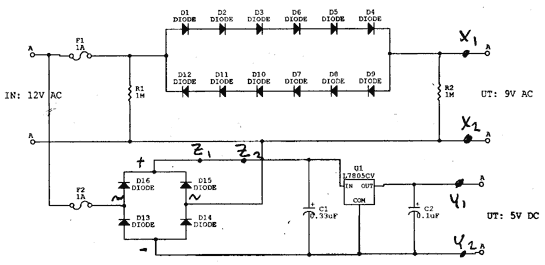
Today, I found his notes. The basis of his design is a ready made 220V to 12V AC, 1-2A transformer, which costs about 70 SEK (8.50 USD) in the electronics store.
Image
My friend comments his design:
We use simple rectifier diodes since they have good characteristics, are cheap and handle heat and cold well. The forward voltage UF is used to convert 12V AC to 9V AC, on behalf that the sinus wave gets somewhat cut off at the 0V level.

The fuses (F1, F2) should be installed on the input side, like the diagram shows. Do not use the inputs like outputs and vice versa.

The resistors (R1, R2) have two functions: together they will work as ESD protection for the diodes. This use is not crucial as rectifier diodes are quite robust and "usually" will survive anyway. The resistor on the output (R2) limits the idle voltage, without it the output voltage will equal or be very, very close to the input voltage when the adapter is completely unloaded.

Between X1 - X2 and Y1 - Y2, two small LEDs |>|´ can be mounted to indicate power function:

X1 -- | 1.2 kOhm | -- |>|´ -- X2

Y1 -- | 470 Ohm | -- |>|´ -- Y2

Between Z1 - Z2, another rectifier diode can be monted to reduce the heat in the heat sink mounted at U1.

Diodes: BY255 or other rectifier diode which can handle IF >= 2.0A with the following forward drop:

UF = 0.8V at IF = 1.0A, UF = 0.6V at IF = 0.1A

The diodes can be mounted in standing position to take less space, preferrably raised a bit from the circuit board. The outer case will not need ventilation holes if the diodes are soldered onto a circuit board.

R1, R2: Resistors 1Mohm
F1, F2: Fuses 1A (he doesn't specify closer than that)
C1, C2: Electrolytic capacitors 0.47 uF/50V (diagram says 0.33 uF ?)
U1: Common voltage regulator 5V, e.g. L7805CV or L78S05CV.

Heat sink: Austerlitz KS29.1-37,5-E or better which handles > 15C/W

Some screws, nuts and cooling paste also required.
Any constructive comments? Please don't make this a flame thread, comparing to any previous "designs" people are not satisfied with. While at the moment I'm not likely to build this kind of power supply, it would be interesting to hear if my friend was thinking in the right direction. The hardest part, to convert a high voltage to 12V would already be solved.
Anders Carlsson

Image Image Image Image Image
User avatar
eslapion
ultimate expander
Posts: 5458
Joined: Fri Jun 23, 2006 7:50 pm
Location: Canada
Occupation: 8bit addict

Post by eslapion »

This plan seems to suffer from the same problem the original Commodore brick does; it uses a linear regulator which lowers the voltage by bleeding the excess off as heat.

Also, there are two very serious problems with that schematic. The first one is obvious, the filtering capacitor before the voltage regulator (0.33uF) is totally insufficient to do the job. You'd need 2200uF or more there.

The second one is less apparent but could destroy your VIC/64. Its because of the way the 9Vac is used in 64s and VIC-CRs. Because your 5Vdc and 9Vac both come from the same source of 12Vac, this would cause a partial short circuit inside the VIC/64 and cause serious damage, especially in a 64 where the 9Vac is rectified and double to create a 12Vdc source for the SID.

As I often mentioned here and on other forums, the sources you use to generate the 9Vac and 5Vdc MUST be floating in relation to one another. The easy way for a hobbyist to do that is to have two different transformers.

I had started a thread about using a switching regulator in a transformer based power supply on Lemon64. Some pretty smart people finished the idea off and the result was quite impressive.

jsaily did something really good and published the results. He uses a switching regulator which boasts an impressive +/- 90% efficiency and the project uses very few parts and is extremely easy for anyone to build.

The thread is here: http://www.lemon64.com/forum/viewtopic. ... highlight=

The final result was a power supply that pretty much any hobbyist can build, is more powerful, produces less heat and is considerably more reliable than any power supply Commodore ever made for any of their 8bit machines.
Be normal.
channelmaniac
Vic 20 Hobbyist
Posts: 105
Joined: Tue Jun 17, 2008 8:21 pm

Post by channelmaniac »

Unless that 7805 is in a TO-3 case it will only be rated for 1 to 1.5A max at 5v. That's not going to be enough.
Call me a cheap bastard... I learned to fix things to save money... even surface mount soldering...

Visit my website: http://www.arcadecomponents.com
Leeeeee
soldering master
Posts: 396
Joined: Fri Apr 23, 2004 8:14 am

Post by Leeeeee »

The TO220 uA78S05 that is used in some VIC 20 PSUs is rated for 2A.

Lee.
channelmaniac
Vic 20 Hobbyist
Posts: 105
Joined: Tue Jun 17, 2008 8:21 pm

Post by channelmaniac »

It's an oddball one. The generic 7805 ICs are rated 1A. Some are 1.5... but you won't find the 2A one at your garden variety Radio Shack store. ;)
Call me a cheap bastard... I learned to fix things to save money... even surface mount soldering...

Visit my website: http://www.arcadecomponents.com
User avatar
eslapion
ultimate expander
Posts: 5458
Joined: Fri Jun 23, 2006 7:50 pm
Location: Canada
Occupation: 8bit addict

Post by eslapion »

If you ask me, the best way to go is to replace the 7805 altogether with a PT78ST105 or other more powerful switching regulators from TI that produce virtually no heat.

Still, if you make a power supply for your 64 or VIC following the general above schematics, it will seriously damage your machine, maybe make it impossible to repair.

The two sources must not be electrically tied to one another. If they are... Kaboom!
Be normal.
Leeeeee
soldering master
Posts: 396
Joined: Fri Apr 23, 2004 8:14 am

Post by Leeeeee »

The two sources must not be electrically tied to one another. If they are... Kaboom!
Not at all true. Look at the PSU in the two pin VIC, there is only the one source.

Lee.
User avatar
eslapion
ultimate expander
Posts: 5458
Joined: Fri Jun 23, 2006 7:50 pm
Location: Canada
Occupation: 8bit addict

Post by eslapion »

Leeeeee wrote:
The two sources must not be electrically tied to one another. If they are... Kaboom!
Not at all true. Look at the PSU in the two pin VIC, there is only the one source.

Lee.
The 2 Prong VIC PSU is only a transformer and a fuse.

The voltage regulator and the rest of the power supply is actually INSIDE the VIC in this particular model so, obviously, none of what's discussed here applies to this model of the VIC-20.
Be normal.
6502dude
megacart
Posts: 1581
Joined: Wed Dec 01, 2004 9:53 am

Post by 6502dude »

The two sources must not be electrically tied to one another. If they are... Kaboom!
Sounds like he is speaking from experience ...... kaboom! :lol: :lol: :lol:
Image Mega-Cart: the ultimate cartridge for your Commodore Vic-20
Leeeeee
soldering master
Posts: 396
Joined: Fri Apr 23, 2004 8:14 am

Post by Leeeeee »

The power supply proposed here is the same form as the internal power supply in the two prong VIC and can safely be used with the DIN power VIC. There is no point in having an isolated AC supply as the two supplies become connected via CR2 inside the VIC.

If you're not going to use the cassette you don't even need the 9VAC. Even if you are you can replace the 9VAC with +12VDC on either or both of the AC pins.

It's not until you get to the C64 that you need AC on one of the the AC power pins and even that does not need to be isolated.

Lee.
User avatar
eslapion
ultimate expander
Posts: 5458
Joined: Fri Jun 23, 2006 7:50 pm
Location: Canada
Occupation: 8bit addict

Post by eslapion »

6502dude wrote:Sounds like he is speaking from experience ...... kaboom! :lol: :lol: :lol:
In fact... yes. :oops:

When I was a teenager, I wanted to make a stronger PSU for my 64 and I used a single huge 9Vac transformer with a big LM323 5V 3A regulator and a big 4700uF capacitor salvaged from a faulty printing calculator.

When I tried the PSU on my 64, I felt the 64 emitted a weird 60Hz buzz and I turned it off. Then when I tried it on my VIC Cr, the main 2200uF capacitor blew up producing an horrible stench and expelling a ribbon of metal and flakes of some sort of mineral wool.

The awful smell was still detectable in my room weeks after the incident. It stuck to the VIC for years after.

I think that was about the first time in my life I used ferric chloride to make my own PCB. It would be more than 20 years until I made another.

Fortunately, I have since then taken a few courses...
:wink:
Last edited by eslapion on Wed Dec 10, 2008 7:02 am, edited 2 times in total.
Be normal.
User avatar
eslapion
ultimate expander
Posts: 5458
Joined: Fri Jun 23, 2006 7:50 pm
Location: Canada
Occupation: 8bit addict

Post by eslapion »

Leeeeee wrote:The power supply proposed here is the same form as the internal power supply in the two prong VIC and can safely be used with the DIN power VIC. There is no point in having an isolated AC supply as the two supplies become connected via CR2 inside the VIC.
The VIC Cr and the 2 prong VIC are totally different inside. Just check the schematics found in the Programmer's reference guide vs those found on zimmers.

Because of the way the 9Vac is retified and used for the TOD clock in the VIC Cr, if your 5Vdc and 9Vac sources aren't floating, you'll cause a short circuit.

Don't use an isolated source for the 9Vac and you'll get the same entertaining experience as I did when I was a teen.

The 2 prong VIC is DESIGNED to operate on a single transformer because that's the way its original PSU was.

All the power supplies made by Commodore for subsequent VIC Crs, 64 and 128s have two independent secondaries FOR A REASON...

Please... give us all a break and stop arguing with facts that are documented and known for the last 25 years.
If you're not going to use the cassette you don't even need the 9VAC. Even if you are you can replace the 9VAC with +12VDC on either or both of the AC pins.
FALSE!

The 9Vac is used for the TOD clock on both the C64 and the VIC Cr. It is also made available on the user port for modems and other special devices. For example, it is rectified and multiplied by the Promenade C1 EPROM programmer to generate the high programming voltages required to program EPROMs (from 12 to 25 volts, depending on the chip programmed)

The Promenade C1 is compatible with both the VIC-20 and C64.

Rectifying voltage multipliers used in both the C64 to power the SID and in the Promenade C1 don't work with DC. They require AC.

Wikipedia: http://en.wikipedia.org/wiki/Voltage_multiplier

The Schematics to the VIC Cr where the power components are located is here.

As you can see, internally, the 9Vac is rectified by diode bridge CR2 and the resulting DC is fed to C39 which is exactly the capacitor that blew up in my VIC when I was a kid.

If you want your VIC Cr to work with a power supply that has a single transformer, you'll have to open it and remove CR2... And THEN you can use it without a datasette without fear of it blowing up in your face.

If you want to do the same with a C64 then it gets even more interesting.

You'll have to forget using a datasette and forfeit the SID too because it won't get its 12V but there's even better... In order to reduce the noise caused by other chips in the video signal, the VIC-II chip has its own independent 5V source which is rectified and regulated from... the 9Vac source. :wink:
Last edited by eslapion on Wed Dec 10, 2008 7:31 am, edited 2 times in total.
Be normal.
Clockmeister
Vic 20 Amateur
Posts: 64
Joined: Mon Oct 06, 2008 7:39 am

Post by Clockmeister »

Leeeeee wrote:The power supply proposed here is the same form as the internal power supply in the two prong VIC and can safely be used with the DIN power VIC. There is no point in having an isolated AC supply as the two supplies become connected via CR2 inside the VIC.

If you're not going to use the cassette you don't even need the 9VAC. Even if you are you can replace the 9VAC with +12VDC on either or both of the AC pins.

It's not until you get to the C64 that you need AC on one of the the AC power pins and even that does not need to be isolated.

Lee.
That is incorrect for all the reasons Eslapion points out.
Leeeeee
soldering master
Posts: 396
Joined: Fri Apr 23, 2004 8:14 am

Post by Leeeeee »

Because of the way the 9Vac is retified and used for the TOD clock in the VIC Cr,
No it isn't. The TOD is a 60Hz interrupt on both PAL and NTSC machines and is generated by VIA 2 T1, the routine that sets this up is at $FE39. No VIC requires AC for the TOD clock.
Don't use an isolated source for the 9Vac and you'll get the same entertaining experience as I did when I was a teen.
I'm sorry that you damaged your VIC, that was unfortunate but wasn't caused by using the same AC winding to supply the rectifier for the DC supply and the VIC's 9VAC supply. Unless you used something like a 9V - 0V - 9V which of course won't work if you try to use both 9V outputs.
Please... give us all a break and stop arguing with facts that are documented and known for the last 25 years.
It is also a 'documented and known' fact that to use an AT PSU on an Amiga you must tie the POWER GOOD pin to 0V. This is also demonstrably wrong.
leeeeee wrote:If you're not going to use the cassette you don't even need the 9VAC.
FALSE!

The 9Vac is used for the TOD clock on both the C64 and the VIC Cr.
No it isn't. If it is please point out where in any of the circuits the 9VAC is used to generate an interrupt because I'm just not seeing it. Neither is my VIC, using just a single +5V supply and repeatedly entering PRINT TI$ shows that the TOD clock is still running.
It is also made available on the user port for modems and other special devices.
I know. I have said nothing about powering external devices this way, just the VIC.
Rectifying voltage multipliers used in both the C64 to power the SID ...
Yes, I know. That's why I said ..
leeeeee wrote:It's not until you get to the C64 that you need AC on one of the the AC power pins
If you want your VIC Cr to work with a power supply that has a single transformer, you'll have to open it and remove CR2... And THEN you can use it without a datasette without fear of it blowing up in your face.
I have a VIC Cr and datasette that have both worked on just an AT PSU. It is wired 5V -> pins 4 and 5, 0V -> pins 1, 2, 3 and 7 (pin 7 is the fused AC input pin) and +12V -> pin 6. Pin 6 is the switched AC input pin, this makes sure that both +5V and +12V supplies are switched together.
If you want to do the same with a C64 then it gets even more interesting.
I know that the C64 needs an AC input on pin 6. This AC can however share a common with the DC supplies and does not need to be isolated.
the VIC-II chip has its own independent 5V source which is rectified and regulated from... the 9Vac source.
The requirements for this would also be met by supplying >~8VDC on pin 6.

Just to be sure I wasn't dreaming all this I unpacked my VIC Cr today and tried the following. Note that for this the datasette was replaced by a link for the switch and an 8V torch bulb for the motor as my datasettes are both in storage.

Powered if from it's own PSU to make sure it was working.

Powered it with just +5V from an AT supply.

Powered it with +5V and +12V from an AT supply.

Everything worked as I expected. With the +12V DC on pin 6 the lamp lit when the datasette motor would have been running and nothing exploded. In fact it is still working now, some four hours later.

There's even a picture of my VIC running on a single +5V supply on my site on this page.
Clockmeister wrote:That is incorrect for all the reasons Eslapion points out.
Unfortunately for Eslapion his teenage error does not make what I can demonstrate to be true false.

Lee.
PaulQ
undead vic
Posts: 1967
Joined: Sun Jan 14, 2007 2:57 pm

Post by PaulQ »

Leeeeee wrote:There's even a picture of my VIC running on a single +5V supply on my site on this page.
As impressed as I am about you running an 8 bit PC card with your Vic 20, I still think that FM radio is a waste of the Vic 20's clock cycles. Even back in the early 80's, FM radios were very common and cheap.
Leeeeee wrote:
Clockmeister wrote:That is incorrect for all the reasons Eslapion points out.
Unfortunately for Eslapion his teenage error does not make what I can demonstrate to be true false.

Lee.
:lol:
Post Reply