Page 7 of 9
Posted: Thu Apr 21, 2011 2:11 pm
by Mike
Here's my attempt at the S-Video mod, done on my CR VIC-20.
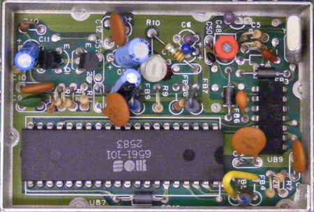
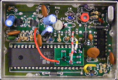
This is the video circuitry before and after the mod. FB7 and the 220 pF capacitor are removed. In place there's now a small board carrying a near exact copy of the luminance amplifying circuit. I used a BC817 SMD small-signal NPN transistor, and a 100 nF decoupling capacitor. The board gets the supply voltages over the red wire (+5V) and black wire (GND). Yellow-white: VIC Pin 2 (chroma) -> amplifier IN. Red-white: amplifier OUT -> mainboard. Note the transistor was soldered 'dead-bug' style, because the layout got mirrored by accident:
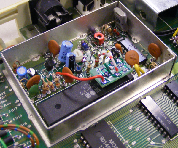
The small circuit board hovers a small distance over the VIC chip:
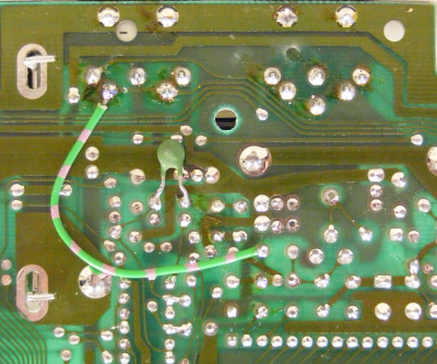
Finally, the chroma signal goes over the pink-green wire to pin 5 of Video Out. Note the trace cut between pins 4 and 5!
Here are screen details of a VFLI image before the mod (left) ... and after the mod (right):


Note how the teared pixels and white/black transients have gone away!
Greetings,
Michael
Posted: Fri Apr 22, 2011 3:28 pm
by Mike
A question from the VFLI thread:
Wilson wrote:why is it that the output of some Vic-20's is worse than others?
The unmodded video output is *always* bad, regardless which version of VIC-20 you use. With the 656x VIC chip, the chroma signal has strong frequency components outside the normal range (for PAL or NTSC). When chroma is mixed with the luminance signal, these off-range components are confused with the luminance signal when they are separated in the display again.
The video circuits differ in which amount chroma is super-imposed on luma. The original VIC-20 mixed a rather low amount in, thus not disturbing the luminance signal too much, but eventually requiring the user to turn up the saturation knob on the TV or monitor. The later CR used a higher amount, distorting the luma signal significantly.
I'm guessing it has something to do with the way the signals are mixed since the S-video mod fixes it?
The S-Video mod prevents the two signals being mixed in the first place. Since the two signals now go on separate ways to the display, the display doesn't anymore need to (try to) separate them, eliminating any cross-talk.
Only for the RF modulator they must be added to form the baseband PAL or NTSC signal.
Is there any way to improve the video signal (without performing the S-video mod) by just changing a capacitor or something like that?
You either have a composite signal (luma+chroma), or separate luma and chroma, i.e. S-Video.
In the OP, a4000bear just made two trace cuts, replaced two components and added a wire on the backside. If you can live with slightly desaturated colours per default (eventually requiring you to turn-up the saturation knob), this is probably the easiest variant on the S-Video mod possible.
Posted: Fri Sep 23, 2011 8:27 am
by rga24
I've just done a full audit of my VIC-20s and will be revisiting this mod for the original VIC-20. The version for the CR with FB7 and C13 intact and a 330R chrominance pulldown resistor remains my favourite version; it's present on the VIC-20 CR I use most often. It "plays nicely" with other CBM hardware including unmodified VIC-20 CRs and C64s in that you don't have to adjust the colour control after swapping out machines.
The version with FB7 and C13 removed has a slight question mark over it that I haven't yet checked, which is that it's not clear which way the 10uF decoupling capacitor should have been connected. This depends on the DC level coming out of the chrominance pin on the VIC chip compared with the bias level on the buffer transistor. In the circuit with C13 present, the pulldown resistor coming after C13 ensures that the chrominance signal at that point has a DC level of 0V. At a guess the chrominance output sits on 2.5V, whereas the base of the transistor is biased at 3V, so it should be fine to connect the capacitor the same way round as in the other mod.
Now I have my best original VIC-20 in front of me, I can see that the video circuit is a lot more complicated but also there is no video shield compartment. So there is a lot more space for a chrominance buffer circuit board. Staying with the design philosophy of the other mod, what I will do is copy the original circuit for composite video and disconnect the chrominance signal on C29 at the point where it would combine with the luminance signal on R33. I won't copy the Q6 current source; this is really for the luminance pin which has an open drain output.
Posted: Sat Sep 24, 2011 10:27 pm
by rga24
I've studied the circuit in the original VIC 20 and I think I understand its operation now, just thought I'd put this description out there to see if anyone else agrees or has any comments.
The reason the colour saturation on the original VIC 20 is lower than on the VIC 20 CR is that on the VIC 20 CR, the point where the chrominance signal is applied to the luminance signal was moved. Not in the schematics as drawn, but in the machines as made. C13 in 251027r1.gif is shown as being connected to R41, R9 and R10 but in the manufactured machines it is connected to the wiper of R10. If you move C29 in 324001_1.gif to the wiper of R7 you would get the same higher level of colour saturation on an original VIC 20, and if you move C13 in 251027r1.gif to the point in the schematic you would get the same lower level of saturation on a VIC 20 CR.
The original circuit combines luminance and chrominance before potentiometer R7, at the point where the current source for the luminance signal is applied. This is made out of R29, C23, Q6 and R19, and pulldown resistance in R7. In the VIC 20 CR the current is provided by a 510 ohm resistor R9, so the current will vary as the voltage at this point changes, whereas in the original circuit the transistor Q6 and the capacitor C23 should provide a more constant source of current regardless of the instantaneous levels of the luminance and chrominance signals. This possibly provides a more linear grey scale for the luminance signal.
In the original circuit, potentiometer R7 provides a gain control for the whole composite video signal, whereas in the VIC 20 CR as made, potentiometer R10 only adjusts the luminance level, the chrominance being applied after the wiper of the pot.
Decoupling capacitor C25 (which may be drawn the wrong way round in the diagram) passes the signal to a bias network and clamp circuit for buffer transistor Q7, made out of R17, R32, R31 and CR2. The diode ensures that the signal applied to the transistor never falls below a value set by potentiometer R32. The range is 2.115V - 4.038V.
Then the signal is buffered by emitter follower Q7, with a 270 ohm load and fed to pin 5 of the video socket directly and to pin 4 via 3.9uH inductor L2 and C18 which together form a low pass filter. I need to confirm the value of C18 from a real machine, the marking is hard to make out on the scanned copy, but I would expect the cutoff frequency to be of the order of 5MHz.
In A4000bear's S-video modifications for the VIC 20 CR pin 4 is the luminance signal and pin 5 carries the new chrominance signal, so for compatibility with that mod it makes sense to do the same here. This is also good because pin 4 carries the filtered signal which I think is intended for direct baseband connection to a 75 ohm load, whereas I seem to recall the RF modulator for the VIC 20 uses the unfiltered signal on pin 5. These are termed VIDEO LOW and VIDEO HIGH in the user manual pinout.
Posted: Sun Sep 25, 2011 3:15 pm
by rga24
Small correction. The circuit with Q6 is not a current source, it's a voltage source. It provides an amount of additional regulation over and above the 5V supply. So the following paragraph should be replaced:
"The original circuit combines luminance and chrominance before potentiometer R7, at the point where the current source for the luminance signal is applied. This is made out of R29, C23, Q6 and R19, and pulldown resistance in R7. In the VIC 20 CR the current is provided by a 510 ohm resistor R9, so the current will vary as the voltage at this point changes, whereas in the original circuit the transistor Q6 and the capacitor C23 should provide a more constant source of current regardless of the instantaneous levels of the luminance and chrominance signals. This possibly provides a more linear grey scale for the luminance signal."
with:
The original circuit combines luminance and chrominance before potentiometer R7, at the point where the pullup current for the luminance signal is applied. A voltage source is made out of R29, C23, Q6 and R19 which provides approximately 4.3V into 470 ohm pullup resistor R19. This provides additional regulation over and above the 5V supply. In the VIC 20 CR the current is provided by a 510 ohm resistor R9 connected directly to the 5V supply.
When the open drain luminance output tries to draw more current from the voltage source, capacitor C23 provides additional base current to turn transistor Q6 on more, rather than let the voltage across base resistor R29 increase. When the luminance output draws less current from the voltage source, surplus base current is put onto capacitor C23 rather than let the voltage across base resistor R29 decrease.
Posted: Sun Oct 23, 2011 10:58 am
by joshuadenmark
Will I get any benefit from this modification when I only have a CRT TV with scart input?
Posted: Sun Oct 23, 2011 12:05 pm
by TLovskog
joshuadenmark:
Depends. The SCART connector was in constant development. One of the additions through time was the support for S-Video. Typically you can select the SCART on your TV to be Composite/S-Video and/or RGB.
Posted: Sun Oct 23, 2011 12:24 pm
by joshuadenmark
Hi Thomas
Thanks for your reply, will look into the specification on my old tv, if I can find it...

Posted: Tue Oct 25, 2011 1:22 am
by TLovskog
Usually you can also find it in the menus. You need to tell the TV what MODE it should be in more or less manually. Some pins in the SCART tells this to some TVs and in some models it doesn't. The SCART is a patch work with a standard that has evolved, some de-facto standards, and alot of brand specific additions.
Posted: Sun Oct 30, 2011 5:59 pm
by rga24
On televisions sold in the UK in the mid 90s, it was common to have two SCART sockets. One was wired for composite and RGB, and the other was wired for composite and S-video. The AV select button on the remote control (or sometimes on the television front panel) would step through the following options: AV-1 (composite), AV-1 RGB, AV-2 (composite), AV-2 S-video.
Old 2 prong mod
Posted: Sun Oct 30, 2011 10:56 pm
by kd7vdb
I modded my Gold label 2 prong Vic and all went good thanks for the instructions!
Posted: Wed Nov 09, 2011 2:30 am
by SparkyNZ
Hi.. I'm looking into getting S-Video output from my Vic and C64.
Obviously I would like to take the simplest path to achieving this. The website below shows a patch cable to convert the C64 DIN output to use S-Video..
http://radagast.bglug.ca/C64_svideo/C64_Svideo.html
Would this not work on a Vic?
I see the original message in this thread started off by showing a relatively simple mod of breaking a couple of tracks and adding a resistor.. Is the reason for all the more complicated solutions due different Vic motherboards? There are so many messages in this thread (many which go right over my head) so I would like to get the low-down if possible.
Thanks
Posted: Wed Nov 09, 2011 4:32 am
by TBCVIC
The Commodore 64 has S-video out already, but the Vic doesn't, so no, that cable won't work.
Yes, there's different Vic motherboards, so you need to adapt the mod to your particular version. Using the schematics in first post in this thread, it's pretty easy to adapt the mod for your particular version of motherboard if you know a little of electronics. I did that and posted it here:
http://sleepingelephant.com/ipw-web/bul ... php?t=3721
Posted: Wed Nov 09, 2011 9:45 am
by Mayhem
As I mentioned, I think maybe over at Lemon64, there was an S-video cable included with the Vic-1001 I bought from Dimitri a number of years back when he had his huge sale. There's a five pin DIN leading to an S-video plug and a mono audio cable, and I get a picture fine on my LCD TV using it.
So if the Vic doesn't naturally output S-video, I wonder what the cable is actually doing then...
Posted: Wed Nov 09, 2011 9:54 am
by Mike
I wonder what the cable is actually doing then...
Quite simple: unless the VIC has been modded, it outputs composite on two pins.
The TV then 'ignores' (most of) the luminance part of the composite signal on its chroma input, and (most of) the chrominance part of the composite signal on its luminance input, by filtering both inputs.
That 'works', somehow. There should still be some distortion of pixels, as some of the chrominance signal is going to be mistaken for luma, and vice versa.