so where is the bug report with testcases?I believe the $9000 and $9001 set to zero-effects are not emulated as well.
6560 FPGA Progress.
Moderator: Moderators
Re: 6560 FPGA Progress.
I'm just a Software Guy who has no Idea how the Hardware works. Don't listen to me.

Re: 6560 FPGA Progress.

Re: 6560 FPGA Progress.
That's not the one, this is the one talked about in the other thread (Raster split and $9002).beamrider wrote: ↑Thu Oct 06, 2022 8:43 amdidn't you add it here?
https://sourceforge.net/p/vice-emu/code ... _9000test/
For the $9001 set to zero-effect see here:
https://sourceforge.net/p/vice-emu/code ... vic_vert0/
I think there is not testcase for $9000 set to zero. However I feel this effect is connected to the thread above as well.
-
JonBrawn

- Vic 20 Devotee
- Posts: 225
- Joined: Sat Sep 11, 2021 10:47 pm
- Website: http://youtube.com/@vicenary
- Location: Austin TX USA
- Occupation: CPU design engineer
Re: 6560 FPGA Progress.
The thing is, if I don't replicate the behavior then I haven't understood the device, and that is what this is about - I'm not creating an FPGA for fame and fortune, I'm creating it so I really grok what's going on inside - I think I've mentioned elsewhere the phrase "experimental archaeology", and that is definitely where I'm coming from.
For example, I've run CHARFLOW-TOKRA on my 6560 and my FPGA, and I've observed the behavior and my FPGA does something completely different, but I can see why the 6560 is doing what it's doing, and I'm going to make sure the FPGA does the same thing in the same circumstances. See a later post about Tokra & Mike's hi-res graphics - there are some fantastic pictures coming!
Working on FPGA replacement for 6560/6561
https://youtube.com/@vicenary
https://youtube.com/@vicenary
-
JonBrawn
- Vic 20 Devotee
- Posts: 225
- Joined: Sat Sep 11, 2021 10:47 pm
- Website: http://youtube.com/@vicenary
- Location: Austin TX USA
- Occupation: CPU design engineer
Re: 6560 FPGA Progress.
Some things will be similar, some things will be different, and based on the 6560, some things will just be plain wild'n'whacky (Exhibit A: 'raster' incrementing half way along a display line)
Working on FPGA replacement for 6560/6561
https://youtube.com/@vicenary
https://youtube.com/@vicenary
-
JonBrawn
- Vic 20 Devotee
- Posts: 225
- Joined: Sat Sep 11, 2021 10:47 pm
- Website: http://youtube.com/@vicenary
- Location: Austin TX USA
- Occupation: CPU design engineer
Re: 6560 FPGA Progress.
Who wants to see a picture of a picture of a tiger?! Everybody LOVES pictures of cats on the Internet, so a picture of a BIG cat must be so much more popular!
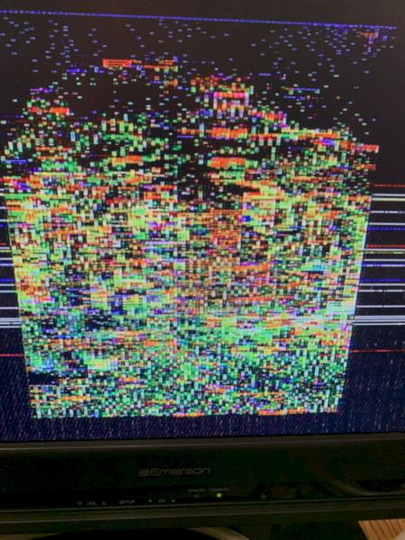
Here is a TIGER:
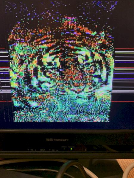
And here is the sad and sorry mess when it's rendered by my FPGA:
In a similar vein, here is a face of a woman (or a bloke in spectacular drag makeup):
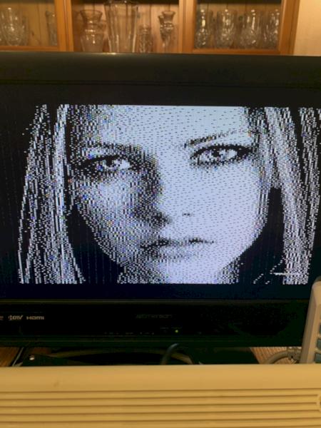
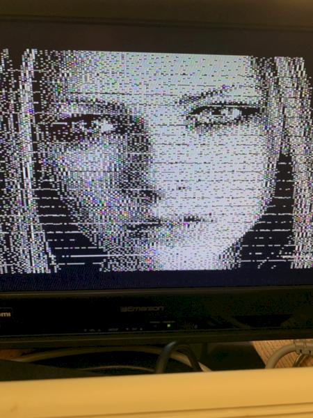
And here she is, standing behind some blinds introduced into the picture by the FPGA:
Mike, Torsten, are you willing to give me some guidance as to how you are generating the images and so how I might be getting it wrong?
Things I can guess are that I've got raster 0 in the wrong place (hence the blinds in the black and white image), and that you're changing something like the screen base or character generator base mid-character, and my timing is wrong.
Looking at the black-and-white image, there are something like 23 "bad lines" on the screen, so that's one per character row, and each "bad line" appears to be two interlaced rasters high. I'm guessing you're flipping screen base or chargen base at the end of each row of characters, based on raster 0 + 8 x R, and so if I've got zero in the wrong place by one line, the wrong data will be displayed at the end (or beginning) of each row. As the bad line is two rasters high, raster 0 is only off by one. Or the position I'm starting the top raster of the display is off by one. More blue tape on the TV screen is needed to check where things line up, and a couple of experimental changes to the alignment of raster 0 and/or the top line of the display area.
Here is a TIGER:
And here is the sad and sorry mess when it's rendered by my FPGA:
In a similar vein, here is a face of a woman (or a bloke in spectacular drag makeup):
And here she is, standing behind some blinds introduced into the picture by the FPGA:
Mike, Torsten, are you willing to give me some guidance as to how you are generating the images and so how I might be getting it wrong?
Things I can guess are that I've got raster 0 in the wrong place (hence the blinds in the black and white image), and that you're changing something like the screen base or character generator base mid-character, and my timing is wrong.
Looking at the black-and-white image, there are something like 23 "bad lines" on the screen, so that's one per character row, and each "bad line" appears to be two interlaced rasters high. I'm guessing you're flipping screen base or chargen base at the end of each row of characters, based on raster 0 + 8 x R, and so if I've got zero in the wrong place by one line, the wrong data will be displayed at the end (or beginning) of each row. As the bad line is two rasters high, raster 0 is only off by one. Or the position I'm starting the top raster of the display is off by one. More blue tape on the TV screen is needed to check where things line up, and a couple of experimental changes to the alignment of raster 0 and/or the top line of the display area.
Working on FPGA replacement for 6560/6561
https://youtube.com/@vicenary
https://youtube.com/@vicenary
-
Mike

- Herr VC
- Posts: 4841
- Joined: Wed Dec 01, 2004 1:57 pm
- Location: Munich, Germany
- Occupation: electrical engineer
Re: 6560 FPGA Progress.
Jon,
one thing beforehand: I replaced your attached photos with new versions that only take 1/1000th of storage footprint. Using up ~60 MB for each of the original photos is completely over the top given what they are just supposed to convey! Please use IrfanView or a similar tool to bring images and photographs into a more palatable size before uploading them here.
tokra and I are doing it this way, because that is the only measure to extend usable screen sizes for a screen bitmap beyond what would only be possible with the internal RAM alone, which then is on the order of 32768 pixels. MINIGRAFIK for example does 160x192 = 30720 pixels but also aims to be OS compliant - therefore it only uses the upper 4K internal RAM for display and no interrupts. The new modes shuffle bitmap data from external RAM into the internal RAM with high-speed transfer code (unrolled loops, etc.). Likewise the colour RAM data is dynamically updated so VIC-I can fetch new attribute data (i.e. foreground colour and multicolour enable state) for each raster. In effect, this gives attribute cells which are not anymore 8x8 (single height characters) or 8x16 (double height characters), but 8x1 pixels!
As you've guessed right, these methods also employ changes of character generator base, and sometimes also of the screen base address.
Some time ago I had prepared tests that check the behaviour of the transitions between non-interlaced and interlaced mode, but I hadn't published the results thus far. I know you already asked about that. I'll prepare a follow-up post, stay tuned ...
Greetings,
Michael
P.S.
You should set the picture aspect ratio to 4:3 instead of 16:9.
one thing beforehand: I replaced your attached photos with new versions that only take 1/1000th of storage footprint. Using up ~60 MB for each of the original photos is completely over the top given what they are just supposed to convey! Please use IrfanView or a similar tool to bring images and photographs into a more palatable size before uploading them here.
In general, all those screenmodes dynamically update character generator data and colour RAM data as the beam races the screen, ensuring that the necessary data is right 'there' in internal RAM when the VIC chip wants to fetch it. Sometimes the correct data arrives in RAM in the cycle before VIC does the fetch, so indeed these modes are all time critical.JonBrawn wrote:Mike, Torsten, are you willing to give me some guidance as to how you are generating the images and so how I might be getting it wrong?
Things I can guess are that I've got raster 0 in the wrong place (hence the blinds in the black and white image), and that you're changing something like the screen base or character generator base mid-character, and my timing is wrong.
tokra and I are doing it this way, because that is the only measure to extend usable screen sizes for a screen bitmap beyond what would only be possible with the internal RAM alone, which then is on the order of 32768 pixels. MINIGRAFIK for example does 160x192 = 30720 pixels but also aims to be OS compliant - therefore it only uses the upper 4K internal RAM for display and no interrupts. The new modes shuffle bitmap data from external RAM into the internal RAM with high-speed transfer code (unrolled loops, etc.). Likewise the colour RAM data is dynamically updated so VIC-I can fetch new attribute data (i.e. foreground colour and multicolour enable state) for each raster. In effect, this gives attribute cells which are not anymore 8x8 (single height characters) or 8x16 (double height characters), but 8x1 pixels!
As you've guessed right, these methods also employ changes of character generator base, and sometimes also of the screen base address.
You should check whether the change from non-interlaced to interlaced mode is done right. In that time, tokra and I used a method to sense the type of field (top or bottom), which ultimately was proven wrong. It actually "works", but because of wrong reasons. Even on original hardware, the blinds in the B/W picture can be made to appear with a 50% chance by activating interlace mode already before activating the new screen mode - i.e. the original method to sense the type of field assumes it starts from non-interlaced mode.Looking at the black-and-white image, there are something like 23 "bad lines" on the screen, so that's one per character row, and each "bad line" appears to be two interlaced rasters high. I'm guessing you're flipping screen base or chargen base at the end of each row of characters, based on raster 0 + 8 x R, and so if I've got zero in the wrong place by one line, the wrong data will be displayed at the end (or beginning) of each row. As the bad line is two rasters high, raster 0 is only off by one. Or the position I'm starting the top raster of the display is off by one. More blue tape on the TV screen is needed to check where things line up, and a couple of experimental changes to the alignment of raster 0 and/or the top line of the display area.
Some time ago I had prepared tests that check the behaviour of the transitions between non-interlaced and interlaced mode, but I hadn't published the results thus far. I know you already asked about that. I'll prepare a follow-up post, stay tuned ...
Greetings,
Michael
P.S.
That's Avril Lavigne.[...] here is a face of a woman [...]
You should set the picture aspect ratio to 4:3 instead of 16:9.
Re: 6560 FPGA Progress.
The timing_ntsc.prg program referred in this post should give a measure of the graphics fetch latency which is crucial for this to work. It does not measure color ram fetch latency though.Mike wrote: ↑Fri Oct 07, 2022 3:13 am In general, all those screenmodes dynamically update character generator data and colour RAM data as the beam races the screen, ensuring that the necessary data is right 'there' in internal RAM when the VIC chip wants to fetch it. Sometimes the correct data arrives in RAM in the cycle before VIC does the fetch, so indeed these modes are all time critical.
-
Mike
- Herr VC
- Posts: 4841
- Joined: Wed Dec 01, 2004 1:57 pm
- Location: Munich, Germany
- Occupation: electrical engineer
Re: 6560 FPGA Progress.
Here we go (download).Mike wrote:Some time ago I had prepared tests that check the behaviour of the transitions between non-interlaced and interlaced mode, but I hadn't published the results thus far. I know you already asked about that. I'll prepare a follow-up post, stay tuned ...
Generally, the tests check the behaviour of $9004/$9003 upon changes to the interlace enable bit in $9000 in raster line 261. It appears there's a single cycle during which the state of $9000 bit 7 is latched, which happens to be between cycles 31 and 32 (counted from 0 as per appearance of that raster number in $9004/$9003 combined). With synchronisation to the start of a raster line, 8 cycles around that 'critical area' are probed - which incidentally is also the period of the LDA $900x:STA $xxxx transfer loops that immediately follow behind to record the values of $9003 and $9004 for 256 cycles.
Here's my interpretation of the screen shots (see ~/results in the *.zip file):
- "4N?XX" and "3N?XX", no-lace to ? (unknown before tests!): If interlace-enable (bit 7 of $9000) is changed from 0 to 1 up to cycle #31 of raster 261 (as of $9004/$9003 combined, and cycle #.. counted from 0):
- raster 261 is extended from 33 to full 65 cycles,
- raster 262 appears with full 65 cycles,
- raster 0 appears with full 65 cycles, and
- raster 1 appears with full 65 cycles ...
If interlace-enable is changed from 0 to 1 in cycle #32 or later of raster 261:
- raster 261 terminates with 33 cycles in total,
- raster 0 appears with 32 cycles,
- raster 1 appears with 65 cycles,
- raster 2 appears with 65 cycles,
- "4TNXX" and "3TNXX", top to no-lace: If interlace-enable (bit 7 of $9000) is changed from 1 to 0 up to cycle #31 of raster 261 (as of $9004/$9003 combined, and cycle #.. counted from 0):
- raster 261 terminates with 33 cycles in total,
- raster 0 immediately appears with 32 cycles,
- raster 1 appears with 65 cycles,
- raster 2 appears with 65 cycles, ...
If interlace-enable is changed from 1 to 0 in cycle #32 or later of raster 261:
- raster 261 retains 65 cycles length,
- raster 262 does not(!) appear,
- raster 0 appears with 65 cycles,
- raster 1 appears with 65 cycles, ...
- "4BNXX" and "3BNXX", bottom to no-lace: If interlace-enable (bit 7 of $9000) is changed from 1 to 0 up to cycle #31 of raster 261 (as of $9004/$9003 combined, and cycle #.. counted from 0):
- raster 261 terminates with 33 cycles in total,
- raster 0 immediately appears with 32 cycles,
- raster 1 appears with 65 cycles,
- raster 2 appears with 65 cycles, ...
If interlace-enable is changed from 1 to 0 in cycle #32 or later of raster 261:
- raster 261 retains 65 cycles length,
- raster 262 does not(!) appear,
- raster 0 appears with 65 cycles,
- raster 1 appears with 65 cycles, ...
Greetings,
Michael
Re: 6560 FPGA Progress.
And when you get to PAL you have the option to test something like this which relies heavily on the exact fetch latency or else the graphics will be misaligned: Impossiblator 3tlr wrote: ↑Fri Oct 07, 2022 6:08 amThe timing_ntsc.prg program referred in this post should give a measure of the graphics fetch latency which is crucial for this to work. It does not measure color ram fetch latency though.Mike wrote: ↑Fri Oct 07, 2022 3:13 am In general, all those screenmodes dynamically update character generator data and colour RAM data as the beam races the screen, ensuring that the necessary data is right 'there' in internal RAM when the VIC chip wants to fetch it. Sometimes the correct data arrives in RAM in the cycle before VIC does the fetch, so indeed these modes are all time critical.
-
Mike
- Herr VC
- Posts: 4841
- Joined: Wed Dec 01, 2004 1:57 pm
- Location: Munich, Germany
- Occupation: electrical engineer
Re: 6560 FPGA Progress.
The colour RAM shares its address pins with the lower 10 bits of the VA address bus. The colour RAM data thus is fetched exactly in the same cycle as the screen codes, in parallel. VIC-I reads the screen codes over BD0..BD7 (pins 16..9) and the colour RAM data over VD8..VD11 (pins 8..5).tlr wrote:It does not measure color ram fetch latency though.
Unlike the VIC-II, neither screen codes nor colour information are cached, and VIC-I re-reads them on every raster line. FLI on the VIC-20 is thus possible without the need to "force" a bad-line condition, as effectively every line already is a bad-line. OTOH, as there's enough memory bandwidth available, that bad-line does not need to stop the CPU.
Note the modes tokra and I designed do not rely on accesses to open memory! All data is fetched by VIC-I from regular internal RAM. The transfer routines ensure the data is there when VIC-I wants to fetch it, sometimes with just a single cycle leeway left. Should a VIC-I replacement want to fetch data from a critical address too early, the display will not just be misaligned, but wrong.And when you get to PAL you have the option to test something like this which relies heavily on the exact fetch latency or else the graphics will be misaligned:
Re: 6560 FPGA Progress.
Yes, my assumption is that the latency is the same but I never measure it directly with that program.Mike wrote: ↑Fri Oct 07, 2022 7:37 amThe colour RAM shares its address pins with the lower 10 bits of the VA address bus. The colour RAM data thus is fetched exactly in the same cycle as the screen codes, in parallel. VIC-I reads the screen codes over BD0..BD7 (pins 16..9) and the colour RAM data over VD8..VD11 (pins 8..5).tlr wrote:It does not measure color ram fetch latency though.
-
JonBrawn
- Vic 20 Devotee
- Posts: 225
- Joined: Sat Sep 11, 2021 10:47 pm
- Website: http://youtube.com/@vicenary
- Location: Austin TX USA
- Occupation: CPU design engineer
Re: 6560 FPGA Progress.
I have fixed Avril's horizontal stripes - when deciding where the top of the text display area should start, you take 2 * $9001 +/- fudge, where fudge can be -1, 0, or 1, and it's essentially a case of "install VIC chip, start the computer, put masking tape on the TV at the transition from cyan border to a white screen, shutdown, install FPGA, see how close you are to the masking tape position, adjust the source code, rebuild, try again. As it's a squint at the screen and judge decision, I was off by one.
Working on FPGA replacement for 6560/6561
https://youtube.com/@vicenary
https://youtube.com/@vicenary
-
JonBrawn
- Vic 20 Devotee
- Posts: 225
- Joined: Sat Sep 11, 2021 10:47 pm
- Website: http://youtube.com/@vicenary
- Location: Austin TX USA
- Occupation: CPU design engineer
Re: 6560 FPGA Progress.
OK, I fully intended to do that, but it was late at night and I forgotMike wrote: ↑Fri Oct 07, 2022 3:13 am one thing beforehand: I replaced your attached photos with new versions that only take 1/1000th of storage footprint. Using up ~60 MB for each of the original photos is completely over the top given what they are just supposed to convey! Please use IrfanView or a similar tool to bring images and photographs into a more palatable size before uploading them here.
Working on FPGA replacement for 6560/6561
https://youtube.com/@vicenary
https://youtube.com/@vicenary
-
JonBrawn
- Vic 20 Devotee
- Posts: 225
- Joined: Sat Sep 11, 2021 10:47 pm
- Website: http://youtube.com/@vicenary
- Location: Austin TX USA
- Occupation: CPU design engineer
Re: 6560 FPGA Progress.
It looks like the FPGA is occasionally reading "bum data," as we industry professionals call it, from memory and getting $FF instead of the correct value. My current thinking is that the pull-up resistors and relatively high capacitance of the cheapo FETs I'm using as level shifters make the data bus voltage marginal in some situations, which is born out when you use either the logic analyzer (there's a lag between when a signal ought to be changing and when it is observed to change, both low-to-high and high-to-low) and with the 'scope where there is a bad slew rate. As it was working the vast majority of the time, I had assumed that it was "just good enough" and was putting off getting some better components and spinning a new board.
Working on FPGA replacement for 6560/6561
https://youtube.com/@vicenary
https://youtube.com/@vicenary