Hoy
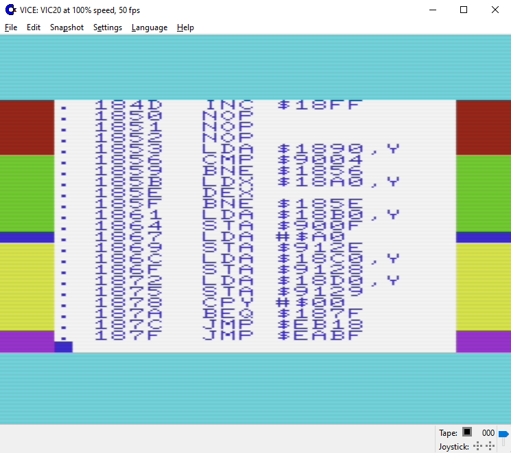
We need some test program that shows the latency of VIA interrupts - something like "start two timers, one of them triggers an interrupt, irq handler reads other timer and shows the value". this one does it for timer A - but somehow due to VIA timers work i couldnt just switch their roles in this program. (if someone sees an obvious error please step up)
Would be cool if someone could step up, i'm busy with other things in VICE atm and i don't know vic20 all too well either...
help with VIA test prog needed
Moderator: Moderators
help with VIA test prog needed
I'm just a Software Guy who has no Idea how the Hardware works. Don't listen to me.

Re: help with VIA test prog needed
Can you clarify what does and doesn't work at the moment? Are you saying that this scenario works
What is the purpose of SHOW? in the NMI handler you're checking against 1 but in the IRQ 0.
- Start T1
- Start T2
- T1 expires, read T2
- Start T2
- Start T1
- T2 expires, read T1
What is the purpose of SHOW? in the NMI handler you're checking against 1 but in the IRQ 0.
Re: help with VIA test prog needed
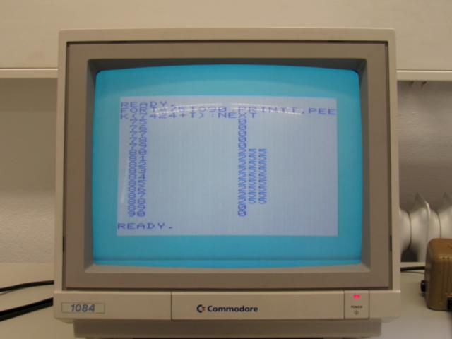
Technically that particular test isnt exactly what we need, it only shows the problem as a sideeffect. What that test does is setting up TWO interrupts, one with each VIA (timer 1). It then starts the two interrupts with different offsets and reads timer 2 (which doesnt generate IRQs) and writes its value to screen. The "SHOW" variable toggles between showing the timer value read in either IRQ handler (simply because both do not fit on the screen - the c64 variant would show both at once). Swapping the timer roles does not work - i think - because Timer 2 can not run in oneshot mode.
For Timer2 we would probably need a new test that only uses one interrupt, and a longer timer period so it can work in continues mode.
For Timer2 we would probably need a new test that only uses one interrupt, and a longer timer period so it can work in continues mode.
I'm just a Software Guy who has no Idea how the Hardware works. Don't listen to me.
-
Mike

- Herr VC
- Posts: 4842
- Joined: Wed Dec 01, 2004 1:57 pm
- Location: Munich, Germany
- Occupation: electrical engineer
Re: help with VIA test prog needed
According to the data sheet, Timer 2 on the VIA only supports one-shot mode, or counting mode on PB6! It does not support continuous mode.
When in one-shot mode, Timer 2 counts down from the start value and issues an interrupt, once, when it underflows to $FFFF. From then on, it loops through the values $FFFF -> $0000 without stopping, but doesn't trigger any interrupt anymore, until it is reloaded - first T2L, then T2C-H which transfers T2L to T2C-L and clears the interrupt flag. The interrupt flag can also be cleared by just reading T2C-L but again no new interrupts will follow.
Furthermore, there's no way to actually stop the timers: Timer 1 in one-shot mode still counts $FFFF -> $0000 similar to T2, with a single interrupt only. In continuous mode, the start value is reloaded from the latch value instead. The other control bit of T1 in ACR just enables or disables output to PB7. T2 could be 'stopped' in counting mode when there's nothing happening on PB6.
In practice, there's always the expected delay of 4 cycles between the two ST% stores that 'start' either of both timers when writing their T1C-H and T2C-H registers, respectively and then the variable delay between raising the interrupt by one of the timers, finishing the currently executing instruction, entering the KERNAL ISR and finally, execute the first instruction(s) of the user interrupt routine. The timers then should keep the 4 cycle distance regardless (modulo Timer 2 continues from $FFFF always and Timer 1 from the latched value if in continuous mode).
Edit: Here's a raster routine (download) I whipped up in a spare hour when we had a discussion here in Denial how to split the screen border (or similar) to different sized regions without hogging the CPU during the whole display frame. I use Timer 1 once per frame in continuous mode (PAL timing!) to initialize the colour change sequence at the bottom of the display window, and Timer 2 in its one-shot mode multiple times to do the other register changes. The whole thing is table based. Start with SYS6144 - this is what you should see in the border:
Re: help with VIA test prog needed
that doesnt really help 
what we want to test is the delay between timer underrun and interrupt, this is supposedly one cycle for one timer, but we need to test the other too. and then in all kind of ways the VIA can generate interrupts (timer modes, shiftregister). an easy way to do this is starting one timer, then produce the interrupt with another (or the SR), and in the interrupt handler read the timer and show it on screen - that will let us check if the emulation is correct easily, and if not also shows in what way its wrong. (and of course the interrupt should fire on a NOP cascade at a defined offset so we have a fixed delay we can take into account)
what we want to test is the delay between timer underrun and interrupt, this is supposedly one cycle for one timer, but we need to test the other too. and then in all kind of ways the VIA can generate interrupts (timer modes, shiftregister). an easy way to do this is starting one timer, then produce the interrupt with another (or the SR), and in the interrupt handler read the timer and show it on screen - that will let us check if the emulation is correct easily, and if not also shows in what way its wrong. (and of course the interrupt should fire on a NOP cascade at a defined offset so we have a fixed delay we can take into account)
I'm just a Software Guy who has no Idea how the Hardware works. Don't listen to me.
-
Mike
- Herr VC
- Posts: 4842
- Joined: Wed Dec 01, 2004 1:57 pm
- Location: Munich, Germany
- Occupation: electrical engineer
Re: help with VIA test prog needed
At least your answer helped me clear up for myself what you really are up to.groepaz wrote:that doesnt really help
Here's an analysis I did quite some time ago where I set up to find the range of possible jitter regarding interrupt handling on first principles - or so I thought:
Code: Select all
NOTE: this table makes the false assumption the interrupt sequence equivalent "BRK" takes 7 cycles -
      actually the interrupt sequence takes 8 cycles, see correct table below!

                                               Bxx        3  $FF, $86..$85
                                    ..$FF      RMW ABS,X  7  $84..$7E
       00        BRK          7  $86..$80                    $7D..$77
.FF72  48        PHA          3  $7F..$7D                    $76..$74
.FF73  8A        TXA          2  $7C..$7B                    $73..$72
.FF74  48        PHA          3  $7A..$78                    $71..$6F
.FF75  98        TYA          2  $77..$76                    $6E..$6D
.FF76  48        PHA          3  $75..$73                    $6C..$6A
.FF77  BA        TSX          2  $72..$71                    $69..$68
.FF78  BD 04 01  LDA $0104,X  4  $70..$6D                    $67..$64
.FF7B  29 10     AND #$10     2  $6C..$6B                    $63..$62
.FF7D  F0 03     BEQ $FF82    3  $6A..$68                    $61..$5F
.FF82  6C 14 03  JMP ($0314)  5  $67..$63                    $5E..$5A
       D8        CLD          2  $62..$61                    $59..$58
       38        SEC          2  $60..$5F                    $57..$56
       A9 xx     LDA #$xx     2  $5E..$5D                    $55..$54
ED 24 91 SBC $9124 4 $5C..$59 $53..$50My theory was the current instruction is completed and when the interrupt is fired while the timer underflows, in the last cycle of that instruction, the CPU will enter the interrupt sequence equivalent to issuing a BRK instruction. Timer 1 is setup with a value of $5686 = 71x312 - 2, so it cycles through $5686, ..., $0000, $FFFF for 22152 cycles each frame (again, PAL timing). This is what you see in the left column.
The right column tried to take the 'hiccup' into account, that when a interrupt fires while a 3-cycle-branch is executed, the 6502 still executes the following instruction before entering the interrupt sequence, and I put a 7-cycle RMW instruction as target to maximize the delay. This is what you see in the right column.
During that analysis I used the values appearing in $9124 (fetched during the last cycle of the SBC instruction) as index to mark their occurrence, with code in the foreground that executed all possible combinations of opcodes to see the whole range of jitter. The maximum value in $9124 I had expected was $59, but when I dumped the table, I got this:
I never got the value $59, instead $58 was the maximum. So the BRK equivalent of the interrupt sequence seems to take one cycle more.
In the 65xx datasheet, they tell that on begin of the interrupt, the 6502 actually performs a read of the opcode byte following the finished instruction, but then throws away this fetch. This makes sense insofar that the CPU has to increment the PC anyway so the interrupt sequence can push the right value for PC and PSR on stack. If you take this into account, the "BRK" interrupt sequence takes actually 8 cycles, not 7. Nothing of that seems attributable to any delays in the VIA, though.
The maximum delay of - counting down to $50 - seems to be in accordance to my analysis on the right side of the table at the start of the posting, 80 is the minimum value or maximum delay/jitter I see. However the right side assumed the interrupt happening in the first cycle of the branch, with the following RMW instruction also executing. With the 8 cycle interrupt sequence, the interpretation is different: when a 3-cycle branch is interrupted in its first cycle, the interrupt sequence commences right after that branch. Only when the 3-cycle branch is interrupted in its 2nd or 3rd cycle, the next instruction is also executed before entering the interrupt sequence.
Here's the corrected table:
Code: Select all
                                               Bxx        3  $00, $FF, $86 ; <- IRQ kicking in on 2nd cycle of branch
                                    ..$FF      RMW ABS,X  7  $85..$7F
       00       "BRK"        _8_ $86..$7F                    $7E..$77
.FF72  48        PHA          3  $7E..$7C                    $76..$74
.FF73  8A        TXA          2  $7B..$7A                    $73..$72
.FF74  48        PHA          3  $79..$77                    $71..$6F
.FF75  98        TYA          2  $76..$75                    $6E..$6D
.FF76  48        PHA          3  $74..$72                    $6C..$6A
.FF77  BA        TSX          2  $71..$70                    $69..$68
.FF78  BD 04 01  LDA $0104,X  4  $6F..$6C                    $67..$64
.FF7B  29 10     AND #$10     2  $6B..$6A                    $63..$62
.FF7D  F0 03     BEQ $FF82    3  $69..$67                    $61..$5F
.FF82  6C 14 03  JMP ($0314)  5  $66..$62                    $5E..$5A
       D8        CLD          2  $61..$60                    $59..$58
       38        SEC          2  $5F..$5E                    $57..$56
       A9 xx     LDA #$xx     2  $5D..$5C                    $55..$54
ED 24 91 SBC $9124 4 $5B..$58 $53..$50Re: help with VIA test prog needed
The 6502 side is all understood (and working correctly)... this is simply about measuring and confirming the +1 cycle introduced by the VIA see https://sourceforge.net/p/vice-emu/code/42183/
I'm just a Software Guy who has no Idea how the Hardware works. Don't listen to me.
-
Mike
- Herr VC
- Posts: 4842
- Joined: Wed Dec 01, 2004 1:57 pm
- Location: Munich, Germany
- Occupation: electrical engineer
Re: help with VIA test prog needed
My analysis is in concordance that the interrupt request actually happens on underflow with the timers - without any delay! -, and the timer value actually also assumes $FFFF in one cycle. From a hardware point of view it is easier to check for a underflow (with an outbound carry signaling that underflow) than to check for the timer value becoming all bits zero - that would require an extra 16-input (N)OR gate whose floor space is better spent elsewhere.
So VICE delaying the interrupt on the VIA timers by one cycle on the assumption the interrupt is supposed to happen when the timer value reaches 0 probably gives the right result for the wrong reasons.
So VICE delaying the interrupt on the VIA timers by one cycle on the assumption the interrupt is supposed to happen when the timer value reaches 0 probably gives the right result for the wrong reasons.
Re: help with VIA test prog needed
And that is why we need test programs
I'm just a Software Guy who has no Idea how the Hardware works. Don't listen to me.
-
Mike
- Herr VC
- Posts: 4842
- Joined: Wed Dec 01, 2004 1:57 pm
- Location: Munich, Germany
- Occupation: electrical engineer
Re: help with VIA test prog needed
The experimentum crucis then would be to set up a timer and interrupt and 'position' an instruction in the foreground so we read the low byte of the timer value just before or after the interrupt was triggered - in the hope we might catch the $FF in the low byte and by the PC on the stack we also get the exact information which instruction was interrupted.
That only leaves us with a lesser problem: reading the low byte also acknowledges the interrupt, the interrupt pulse then might be too short for the 6502 to accept it.
That only leaves us with a lesser problem: reading the low byte also acknowledges the interrupt, the interrupt pulse then might be too short for the 6502 to accept it.
Re: help with VIA test prog needed
That'd be an interesting detail test... but just to prove the observation of having this delay or not, what i said before is sufficient
I'm just a Software Guy who has no Idea how the Hardware works. Don't listen to me.

Re: help with VIA test prog needed
Very hard-core technical discussion here... 
I don't know if is the right place to ask but I have a 6522 VIA curiosity for the VIC-20 about locations $9116 (VIA1T1LL) and $9117 (VIA1T1LH), by using VICE the values for these locations are $FF $DF for both PAL and NTSC but I don't understand if, how and where they are initialized, It's just a VIA 6522 default value on Power up?
I'm asking because you may change these addresses apparently without problems at least if you don't use RS232 software, and these values do not change even if you reset the machine but only if you switch off the Vic-20, so how is supposed to use these locations?
Mega-Cart: the cartridge you plug in once and for all.
Re: help with VIA test prog needed
The Rockwell datasheet states that the timer latches and counters are not affected by a reset. I guess they the timers just keep running with a random value until explicitly set.
Re: help with VIA test prog needed
see https://sourceforge.net/p/vice-emu/code ... _defaults/
feel free to explore more The most interesting thing would be making this program work from some cartridge (so any init stuff done by the kernal can be skipped hopefully) so we can see the powerup values and perhaps also reset values then. I dont have any flash-cartridge for vic20, so i am out there
feel free to explore more
I'm just a Software Guy who has no Idea how the Hardware works. Don't listen to me.
Re: help with VIA test prog needed
I've briefly modified the code to add $A000 header but I don't know how to interpreter the screen results in vice.
I've not checked the code but I guess it requires some modifies to run without any kernal initialization.
In case, I have an hacked cart that works with a 27C64, It's easy for me to test it from PAL, if it works of course.
I've attached modified sources and rom image.
I've not checked the code but I guess it requires some modifies to run without any kernal initialization.
In case, I have an hacked cart that works with a 27C64, It's easy for me to test it from PAL, if it works of course.
I've attached modified sources and rom image.
- Attachments
-
- main_cart.zip
- (2.27 KiB) Downloaded 85 times
-
Mega-Cart: the cartridge you plug in once and for all.