Help - Relay switch design

Modding and Technical Issues

Moderator: Moderators

Post Reply
OBSysteme
Vic 20 Enthusiast
Posts: 156
Joined: Fri Jul 23, 2010 8:56 pm

Help - Relay switch design

Post by OBSysteme »

Hi , I am getting interested in building a relay device from scratch and would like some help from the hardware folks, to understand and make sure I get a first prototype switch to work right from the User port, and not damage the VIC.

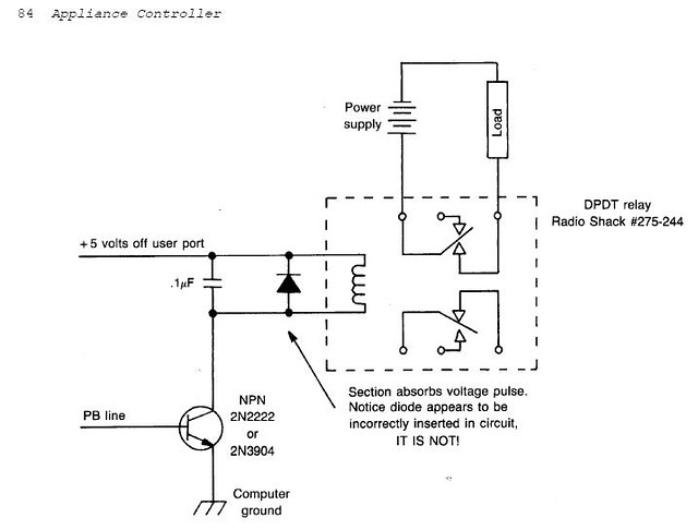
I initially went on a search and apparently found the exact circuit design I needed, which can be found here: http://www.atariarchives.org/ecp/chapter_8.php
On there, there is design for Vic-20, and also an altered version for Atari computers...

Here’s the design for a single switch circuit which lights an LED:
Image

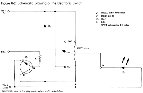
Now, I have poor knowledge of electronics, but the more I look at this design, the more I get puzzled... At first glance, the circuit looks like a demo which lights a LED using the Vic’s own 5volt Current. No problem there.... but then their guidelines say that if you want to hook a device to be controlled by the VIC, to hook it up at the two points labelled “A
PhilRanger
Vic 20 Hobbyist
Posts: 143
Joined: Thu Aug 25, 2011 10:04 am

Re: Help - Relay switch design

Post by PhilRanger »

Image

Hi!

Disconnect the NC from the Vic's 5V and connect it to your power (I assume 120V or 220V?). Disconnect the other side of your load and connect it to the remaining side of your power. I think that with this setup, when the Vic is off, the load will be on!

Hope you'll have fun. Please always be safe when doing these: I suggest trying first replacing the high power source and load by a couple of AA batteries and a flash light bulb before connecting any high power close to a Vic!
Phil Ranger
-------------
"Don't eat the trees 2" for the VIC 20 : http://www.box.net/shared/u398kj0nr0lkauzm1k67
on line: http://www.mdawson.net/vic20chrome/vic2 ... otrees.prg
PhilRanger
Vic 20 Hobbyist
Posts: 143
Joined: Thu Aug 25, 2011 10:04 am

Post by PhilRanger »

Hi again...

Someone can probably confirm or correct but:

1- Connecting to the NC of the relay means relay OFF = load ON (this one I'm sure)

2- If you connect to NO instead then relay on = load on BUT... I think by default when you'll switch the VIC on the relay will become "ON" until you send the command to turn it off. This is often the case with memory circuits and it is probably why they connected it to NC instead of NO. (To be confirmed in this case)
Phil Ranger
-------------
"Don't eat the trees 2" for the VIC 20 : http://www.box.net/shared/u398kj0nr0lkauzm1k67
on line: http://www.mdawson.net/vic20chrome/vic2 ... otrees.prg
OBSysteme
Vic 20 Enthusiast
Posts: 156
Joined: Fri Jul 23, 2010 8:56 pm

Post by OBSysteme »

Thanks Phil!!!!

your suggested mod makes more sence and looks like the way I envisaged, regarding the pins of the Relay.

I guess I can remove the LED from its current suggested location and try it elsewhere if I want it to be triggered by Vic's power source.

Good suggestion for the battery mock-up for testing. I will no doupt make myself a little "fake device" for testing, but also the types of devices I plan to control with it will not by high voltage (3 volt, 5 volt, maybe 12 volt some cases).
PhilRanger
Vic 20 Hobbyist
Posts: 143
Joined: Thu Aug 25, 2011 10:04 am

Post by PhilRanger »

No Problem. By the way, the led is in the wrong direction and you need some resistor in series with it otherwise it will burn quickly (I suggest 220 Ohms)

Using a PNP instead of a NPN might solve the inversion problem if it exists. A simple way to check is to put a voltmeter between the user port pin and the ground and check if by default it is close to 5 volts or close to 0 volts.

Let me know if the inversion problem exists and I'll do a quick schematics of the PNP solution

Make sure your relay has a 5 volt coil with a relatively low current.

Cheers

Phil
Phil Ranger
-------------
"Don't eat the trees 2" for the VIC 20 : http://www.box.net/shared/u398kj0nr0lkauzm1k67
on line: http://www.mdawson.net/vic20chrome/vic2 ... otrees.prg
OBSysteme
Vic 20 Enthusiast
Posts: 156
Joined: Fri Jul 23, 2010 8:56 pm

Post by OBSysteme »

Thanks,

I think I can try this on relatively short notice when I get the time, by scavenging parts from a pile of junk Winmodems I have here. The relays on most of these cards seems to fit the criteria you recommend.
OBSysteme
Vic 20 Enthusiast
Posts: 156
Joined: Fri Jul 23, 2010 8:56 pm

Post by OBSysteme »

I’ve searched around to see what I have available already with regard to parts, and I don’t have the exact same parts as suggested in that book’s schematic, but here is what I have handy, which may be equivalents or close enough:

5V coil relay: I have
Resistors 2.2k and 220 ohm: I have
Diode: use 1N4148 instead of 1N914 ?
NPN small signal transistor: I have some 2N3904 that could be used instead of 2N2222 ?

From what I’ve read, 2N2222 can switch 3 times more current than 2N3904... I don’t know if the VIC’s current output is over the 2N3904’s threshold, such that 2N3904 would be inadequate?

It seems that 2N3904 is optimised for 10mA current, while 2N2222 is for 150mA? However, on the 2N3904 documentation, it says 2N3904 can be used with up to 100mA
http://www.fairchildsemi.com/ds/2N/2N3904.pdf

Would simply changing the 2.2k resistor for one with a higher value be the solution for using 2N3904?

Concerning resistors, is it risky to use 1/8 Watt resistors with the VIC user port? I’ve read somewhere that as long as your resistor values are not under 220 Ohm and that voltage is 9Volt or less, that 1/8 and 1/4 are safe to use.

Thanks again for any help with this!
PhilRanger
Vic 20 Hobbyist
Posts: 143
Joined: Thu Aug 25, 2011 10:04 am

Post by PhilRanger »

OBSysteme wrote:5V coil relay: I have
Resistors 2.2k and 220 ohm: I have
Diode: use 1N4148 instead of 1N914 ?
NPN small signal transistor: I have some 2N3904 that could be used instead of 2N2222 ?
diode: good, they are both fast
2n3904:should work, may overheat with time depending on how much current the relay coil draws (see below to optimize)
From what I’ve read, 2N2222 can switch 3 times more current than 2N3904... I don’t know if the VIC’s current output is over the 2N3904’s threshold, such that 2N3904 would be inadequate?

It seems that 2N3904 is optimised for 10mA current, while 2N2222 is for 150mA? However, on the 2N3904 documentation, it says 2N3904 can be used with up to 100mA
http://www.fairchildsemi.com/ds/2N/2N3904.pdf


Would simply changing the 2.2k resistor for one with a higher value be the solution for using 2N3904?
Keep 2.2k on the base to avoid too much current in the base. A good check: when the relay is ON, the voltage across the coil needs to be close to 5V, or at least 4.5V. If it is lower than 4.5V, put 2 resistors in parallel on the base (2.2k in parallel with 2.2k = 1.1k), but I don't think you'll need to do this. If it doesn't help, you may need to put 2 transistors in parallel (once again this is quite unlikely).
Concerning resistors, is it risky to use 1/8 Watt resistors with the VIC user port? I’ve read somewhere that as long as your resistor values are not under 220 Ohm and that voltage is 9Volt or less, that 1/8 and 1/4 are safe to use.
Thanks again for any help with this!
5V in 2.2k = 11 mW, so don't worry about it. Your 220 Ohms is ok as long as it is in series with the led, but it may be a bit hot.

So basically: go ahead, have fun!
Phil Ranger
-------------
"Don't eat the trees 2" for the VIC 20 : http://www.box.net/shared/u398kj0nr0lkauzm1k67
on line: http://www.mdawson.net/vic20chrome/vic2 ... otrees.prg
User avatar
darkatx
Vic 20 Afficionado
Posts: 471
Joined: Wed Feb 04, 2009 2:17 pm
Location: Canada

Post by darkatx »

I am by no means an electronics expert but there is a book (I happened to stumble across and scan) Electronics Projects for your Commodore 64 and 128. It even has ports for Vic-20 as well. Neat book and chapter 7 called appliance controller is pretty close to what you are after with some keen info on circuit construction and obvious safety advice. ;)

http://www.bombjack.org/commodore/books.htm
(A purple book - you'll find it under the Hardware section)
Learning all the time... :)
OBSysteme
Vic 20 Enthusiast
Posts: 156
Joined: Fri Jul 23, 2010 8:56 pm

Post by OBSysteme »

darkatx!

nice suggestion! I found what you refered to, image on page 48 of Lovine 1989:

Image

I can see on there our friend 2N3904, listed as alternative to 2N2222, which backs up Phil's reassurances.

It is intreaguing that the resistor on this schematic in not located at the same place and bridges with the 5+ volt?

Also, this is not related, but here is a link to the Vic-20 interfacing blue book, for anyone interrested in vic interfacing hardware and who may not have encountered it yet (many cool products in there as well):

http://www.1000bit.it/support/manuali/c ... e_Book.pdf

darn, there are so many of those commodore guide books of all kind, it is quite insane....
PhilRanger
Vic 20 Hobbyist
Posts: 143
Joined: Thu Aug 25, 2011 10:04 am

Post by PhilRanger »

I would think that without a resistor on the base you will destroy your user port, although I don't know in how much time. I don't think the capacitor is needed if you have a fast diode but it doesn't hurt. I also don't see the resistor you're talking about in the new diagram...
Phil Ranger
-------------
"Don't eat the trees 2" for the VIC 20 : http://www.box.net/shared/u398kj0nr0lkauzm1k67
on line: http://www.mdawson.net/vic20chrome/vic2 ... otrees.prg
OBSysteme
Vic 20 Enthusiast
Posts: 156
Joined: Fri Jul 23, 2010 8:56 pm

Post by OBSysteme »

Phil,

Oh I mis-interpreted the capacitor for a resistor.
Post Reply