well my 2114s arrived and i proceeded to change the ram chips to fix my garbled text on screen problem.
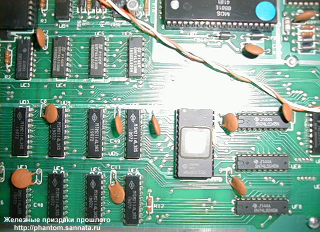
i decided to change UE5 & 6 and immediately above UD5 & 6 first
as i found that area to respond well to a spray of freeze.
http://phantom.sannata.ru/museum/img/co ... ic20_6.jpg
i soldered in sockets and changed and tested each chip one at a time. tested each socket leg for adjacent leg short circuits. UE6 and UE5 were ok, vic boots to logo and i can type,but after a few moments the screen garble reappears. so i moved on to UD6.
i put in a socket and a new 2114 in UD6 and power on - Blank screen
i put the old 2114 back in the UD6 socket , still get blank screen. i move of the new 2114s from UE6 - still blank screen.
I notice that if i power up with NO chip in socket UD6 the vic turns on, and instead of the blank screen i get a screenful of characters: http://www.geocities.com/komodorecomrade/garbled.jpg
i unsoldered the socket in UD6 and soldered in a new socket.redid the above tests with same results. even tryed putting back all of the old 2114s.same results.i proceeded to fix a socket in UD5 as well and put in all new 2114s in UD5/6 & UE5/6. same results.
what have i done to the pcb UD6? or have i overheated anything through the pcb (901460-03 char ROM to its right?) what can i try next/test to diagnose what is wrong? thanks
Konrad
help! I've killed my vic!
Moderator: Moderators
-
komodorecomrade
- Vic 20 Newbie
- Posts: 18
- Joined: Thu Jun 09, 2005 2:27 pm
In addition to checking for shorts between address lines on UD6, also check to make sure there is continuity from foil side to pcb trace to each pin in socket you have installed for each ram chip. Do this testing with chip not installed in socket.
Sometimes traces will crack or foil will burn off when replacing chips (if too much heat is applied to pcb foil side).
If you have a open data line or address line, you can get the garbage characters. Open data bus lines or address at chip will tend to float giving erratic results (garbage).
Hope this helps.
-
komodorecomrade
- Vic 20 Newbie
- Posts: 18
- Joined: Thu Jun 09, 2005 2:27 pm
i guess i might have extracted a trace between the two sides when pulling out the old IC
i was soldering the socket in from the bottom side only. so the top side was not getting the contact needed. i removed the socket and soldered in the chip directly and its working great now
the sockets used in vics dont have enough clearance to solder underneath them. are there sockets with extra long legs for this? or do you usually just run some solder in the defective hole to connect both sides again?
many thanks,
Konrad
Traces on top side of board (under chip/socket) can be tricky when swapping out chips. I typically use a pair of side cutters to break old chip apart and desolder one pin at a time, removing the waste old chip fragments as I go. This helps minimize damage to circuit board.
I also test with multimeter for continunity from traces to pin holes, prior to soldering in socket for replacement chip. I have found that spending a bit more time on the prep work has saved me lots of trouble shooting / head scratching hours.
Once socket is installed and provided the trace is okay on the top side, heating pin on foil side of circuit board and allowing solder to wick up to top side trace will generally restore continuity.
Congrats on fixing chip replacement problem.
Is your orginal Vic-20 problem now cured?
-
komodorecomrade
- Vic 20 Newbie
- Posts: 18
- Joined: Thu Jun 09, 2005 2:27 pm


Doesn't sound like a hardware problem with just one key bad.
To verify, try swapping the 6522 chips. If problem with ";" goes away then you need a replacement 6522. These are easy to obtain for about $5USD.
If problem still exists, you will need to disassemble and clean key contacts.
No big deal - use alcohol the drug store (not the drinkin' kind )
)
To verify, try swapping the 6522 chips. If problem with ";" goes away then you need a replacement 6522. These are easy to obtain for about $5USD.
If problem still exists, you will need to disassemble and clean key contacts.
No big deal - use alcohol the drug store (not the drinkin' kind
-
Guest
-
Guest
yes it turns out its the key thats bad.
the function key definintion idea, would this be like a keyboard interrupt handler which could be active during basic programming?
i could load the program off a tape before any lengthy coding session.
...if this is turning into a major software project then maybe ill just try rewiring that button to the pound key...
thanks