Since almost all of us are embracing the MMC/SD memory cards these days, I would need some advice. The same day I received the uIEC's from Jim, just for laugh I also bid on a homemade device and won it.
http://www.tradera.com/auction/auction. ... d=84366732
(never mind it says Commodore 64, I'm sure it would work just as well on a VIC-20)
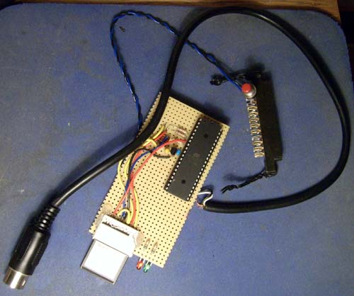
It suggests it would be a MMC2IEC derivate, which is correct as far as the big chip is an ATMEGA32. However I've spent some time looking at schematics and barely can made head or tails. The number of resistors and capacitors, their values and positions don't quite match the MMC2IEC. This thing has a transistor, but no clock crystal.
I can take more high resolution images of both the top and bottom sides if anyone wants to have a look. The light grey cable has three leads, the black and blue cable only two which I presume is for voltage (3.3V or 5V?) and ground.
Possibly it is just a bit of junk best reused for parts. I remember a year ago I found some website with a home-made quite primitive MMC/SD interface, much simpler than either of those 1541-III, MMC2IEC, sd2iec, uIEC/SD, MMC64, MMC Replay, 1541 Ultimate and whichever else I forgot. However at the moment I can't find that particular website again so I can't check its schematics.
I presume I could take the ATMEGA32 out of its socket and perhaps read it in my EPROM reader/programmer to see what is on it and compare with firmwares floating around?
Identify this SD interface (semi off-topic)
Moderator: Moderators
Identify this SD interface (semi off-topic)
Anders Carlsson


Re: Identify this SD interface (semi off-topic)
That would be my guess too.carlsson wrote:It suggests it would be a MMC2IEC derivate, which is correct as far as the big chip is an ATMEGA32.
Most likely a 3.0 to 3.3V regulator because it's located right next to one set of the power pins of the AVR and it has two filtering caps next to it. A crystal is not required if you use the internal RC oscillator of the chip, the standard IEC protocol is quite forgiving when it comes to clock speed errors.This thing has a transistor, but no clock crystal.
I can take more high resolution images of both the top and bottom sides if anyone wants to have a look.
Probably 5V. The resistors on there look like they're connected as voltage dividers to reduce the AVR outputs to a range that is compatible with the card.The light grey cable has three leads, the black and blue cable only two which I presume is for voltage (3.3V or 5V?) and ground.
I think a low-cost MMC2IEC clone is already the simplest [is that an english word?] implementation you can get - just a microcontroller, six resistors for interfacing the card and a voltage regulator plus caps to generate its supply voltage (or two diodes and no caps if you don't care about data sheets...). The board you have seems to be the "luxury version" of that with two LEDs.I remember a year ago I found some website with a home-made quite primitive MMC/SD interface, much simpler than either of those 1541-III, MMC2IEC, sd2iec, uIEC/SD, MMC64, MMC Replay, 1541 Ultimate and whichever else I forgot.
If your EPROM programmer can read 40 pin microcontrollers (mine can't) that should be possible.I presume I could take the ATMEGA32 out of its socket and perhaps read it in my EPROM reader/programmer to see what is on it and compare with firmwares floating around?
I have borrowed an ALL-11P from Hi-Lo Systems. It takes 40-pin chips. I read the ATMEGA and indeed it contains MMC2IEC DOS V0.8.
I had another look at Lars' schematics and realized he uses a 44-pin TQFP chip although graphically it looks very much like a DIP. It means I have to translate all the pin numbers:
TQPF-44
GND = pins 6, 18, 39
VCC = pins 5, 17, 38
IECATN = pin 19 (PC0)
IECDATA =pin 20 (PC1)
IECCLOCK = pin 21 (PC2)
DIP-40
GND = pins 11, 31
VCC = pin 10 (AVCC on pin 30)
IECATN = pin 22 (PC0)
IECDATA = pin 21 (PC1)
IECCLOCK = pin 20 (PC2)
Suddenly at least the wiring makes sense. Now the question is whether I dare connecting this to some Commodore computer.
I had another look at Lars' schematics and realized he uses a 44-pin TQFP chip although graphically it looks very much like a DIP.
TQPF-44
GND = pins 6, 18, 39
VCC = pins 5, 17, 38
IECATN = pin 19 (PC0)
IECDATA =pin 20 (PC1)
IECCLOCK = pin 21 (PC2)
DIP-40
GND = pins 11, 31
VCC = pin 10 (AVCC on pin 30)
IECATN = pin 22 (PC0)
IECDATA = pin 21 (PC1)
IECCLOCK = pin 20 (PC2)
Suddenly at least the wiring makes sense. Now the question is whether I dare connecting this to some Commodore computer.
Anders Carlsson
Okie, I soldered the 5V and GND pins to a userport connector then used a leftover female DIN for the other three wires. One of the LEDs light up, and I ran this program to read the error channel:
10 OPEN1,8,15:INPUT#1,E,E$,T,S
20 PRINTE,E$,T,S:CLOSE1
It reports "73 MMC2IEC DOS V0.8 0 0" so at least something is working. According to the docs I should LOAD"<- <-",8 (two back arrows). The result of this operation is "0 ERROR: FILE SYSTEM". However Windows reports this 16 MB (!) MMC card to be formatted as FAT (not FAT32) which is what MMC2IEC expects. Hm.
Oh and by the way, this device completely hates Action Replay Fastload mode, it just hangs. I'll see if e.g. EasyLoad is better accepted.
Update: For fun, I tried a 256 MB card formatted as FAT32 instead. Voila, it works perfectly. Very strange, as I got the impression it needed to be FAT16.
10 OPEN1,8,15:INPUT#1,E,E$,T,S
20 PRINTE,E$,T,S:CLOSE1
It reports "73 MMC2IEC DOS V0.8 0 0" so at least something is working. According to the docs I should LOAD"<- <-",8 (two back arrows). The result of this operation is "0 ERROR: FILE SYSTEM". However Windows reports this 16 MB (!) MMC card to be formatted as FAT (not FAT32) which is what MMC2IEC expects. Hm.
Oh and by the way, this device completely hates Action Replay Fastload mode, it just hangs. I'll see if e.g. EasyLoad is better accepted.
Update: For fun, I tried a 256 MB card formatted as FAT32 instead. Voila, it works perfectly.
Anders Carlsson