A capture of scanline 55 including the sync, colorburst, and all 4 chracters looks like this:

I can clearly see the luma signal beginning with the sync, then the black border, then 4 spaces of different luminance. You can also notice only the first 3 spaces have a color signal since the 4th one is white.
I then realized the phase of the colorburst signal is inverted on every video field. The colorburst cannot be captured properly by averaging samples because they cancel each other to zero. I decided to make 2 close up captures right after the sync ends; one for each phase.
Phase A:

Phase B:

This is the most detailed close-up of the colorburst I can give. There is a lot of noise in there and the noise is sync to the colorburst so I assume it comes from the VIC. I used a 20MHz filter to reduce garbage as much as possible.

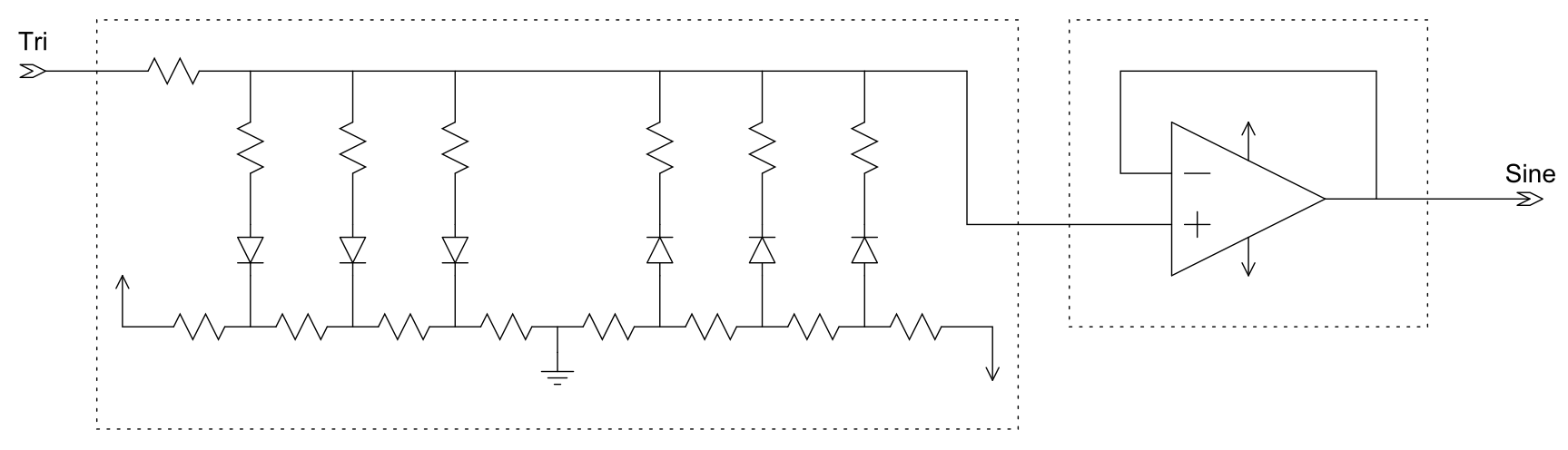
It looks like a poor man's sine wave that could either be done with a wave shaper or double integration. Given the choice, I would do it with a wave shaper as it requires much fewer discreet components than a pair of integrators.