S-Video from the VIC

Modding and Technical Issues

Moderator: Moderators

Post Reply
a4000bear
Vic 20 Amateur
Posts: 57
Joined: Sun Jan 27, 2008 10:01 pm
Location: Australia

S-Video from the VIC

Post by a4000bear »

Here it is: S-Video from the VIC.

Firstly the usual disclaimer:
Do not perform this mod unless you are have a good knowledge of electronics. Remember to perform the usual antistatic procedures. Bear in mind your VIC may be a different version to the one shown here. And of course, I will not be held responsible if you damage your VIC.

The modification assumes you are using a later model VIC...with a version "N" PCB. This is the most common type. This is the one with the coloured VIC logo on the case.

The modified circuit is shown below. My VIC was different from the circuit below in that R8 shown connected to pin 3 was not present. Should you find you have insufficient contrast in your picture or its a bit blurry, short this resistor out.

The variable resistor, R10 will still function, allowing you to adjust the luminance level as before. If you have an oscilloscope, adjust this resistor to give a Y signal level of 1 volt from sync tip to white, while your monitor is connected. Do not adjust the resistor unless you have an oscilloscope, or your picture is excessivly dark or bright, in which case adjust it for a normal looking picture with your brightness and contrast controls set to their normal positions. This note also applies if you have an unmodified VIC and you want to play with this control.

Image

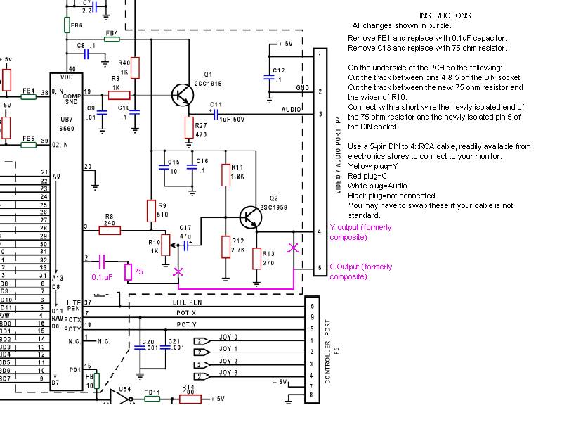
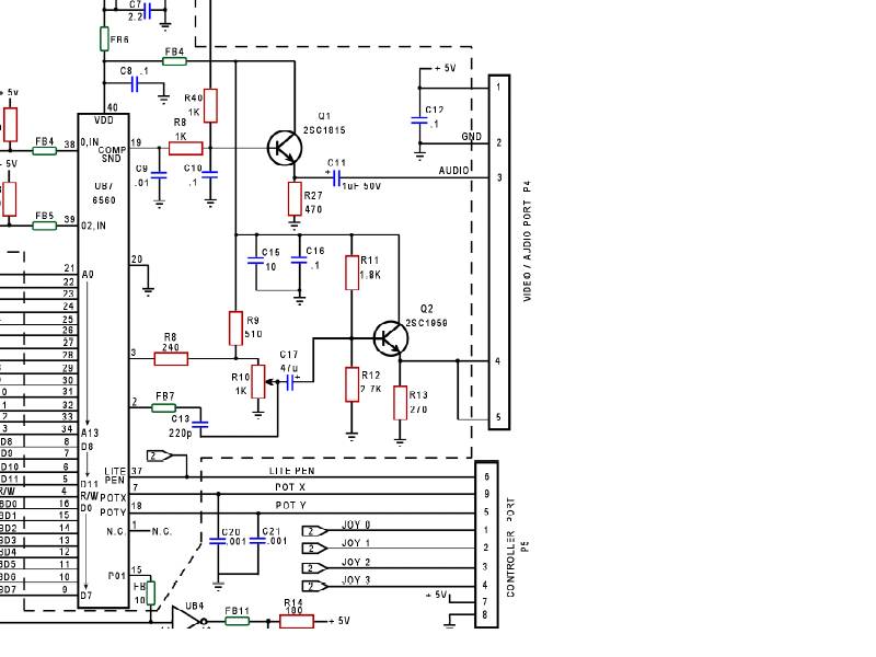
Below is the unmodified circuit.

Image

This is a view of the modified VIC from the component side, the two component changes are outlined in red. As you can see its very hard to spot the difference from an unmodified VIC.

Image

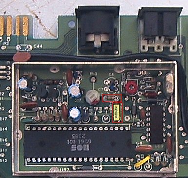
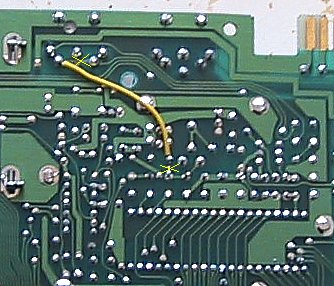
This is a view of the PCB showing the added wire and the location of the two cuts to the PCB tracks.

Image

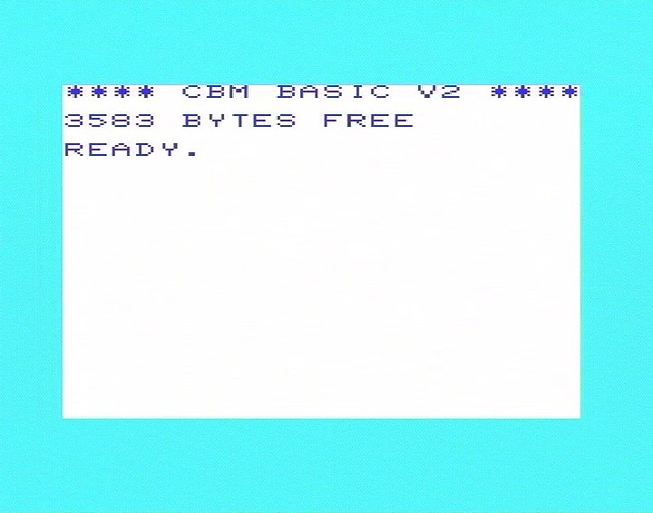
Below are some samples of how the VIC display looks in S-video. These were fed into a timebase corrector to interlace the video, then the interlaced video was fed into an Amiga 4000T with a VLAB video digitiser card. The picture looks slighty better on an analogue screen as there is no aliasing effect between the VIC-sized pixels and the pixels in the VLAB digitiser. The effect is most noticeable in the 'M' in CBM.

Unfortunately I do not have any 'before' shots as I had modified the VIC several years ago, and do not want to unmodify it. You might instead compare your standard VIC display with these pics before deciding to do the modification.

Here is the standard VIC startup screen as it appears in S-Video:

Image

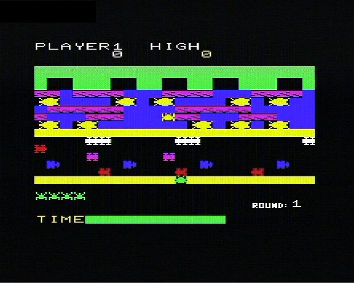
And here is Frogger as it appears in S-Video:

Image
Last edited by Mike on Fri Aug 18, 2023 2:07 am, edited 5 times in total.
Reason: broken image links restored from archive.org
dave01253
Vic 20 Dabbler
Posts: 94
Joined: Thu Mar 08, 2007 2:19 pm

Post by dave01253 »

did you take any photos of the display before and after your mod ?

I think I'm going to dig out my soldering iron !
a4000bear
Vic 20 Amateur
Posts: 57
Joined: Sun Jan 27, 2008 10:01 pm
Location: Australia

Post by a4000bear »

dave01253 wrote:did you take any photos of the display before and after your mod ?

I think I'm going to dig out my soldering iron !
No, but I will say there is no more of that vertical banding, and there is no 'dot crawl' between different coloured areas. The picture is also sharper. :-)
User avatar
ral-clan
plays wooden flutes
Posts: 3702
Joined: Thu Jan 26, 2006 2:01 pm
Location: Canada

Post by ral-clan »

Thanks very MUCH for the well done instructions.

I may try this on one of my "rainbow" logo VICs. Unfortunately the main VIC I use is an older model (with the brass sticker). I prefer it though as it was my actual VIC from 1982.

So, I guess if Eslapion makes that riser board mod he was talking about I'll buy one of those from him for my older VIC.
a4000bear
Vic 20 Amateur
Posts: 57
Joined: Sun Jan 27, 2008 10:01 pm
Location: Australia

Post by a4000bear »

ral-clan wrote:Thanks very MUCH for the well done instructions.

I may try this on one of my "rainbow" logo VICs. Unfortunately the main VIC I use is an older model (with the brass sticker). I prefer it though as it was my actualy VIC from the 1982.

So, I guess if Eslapion makes that riser board mod he was talking about I'll buy one of those from him for my older VIC.
Yes, the riser board version is better for the older VICs as the chips are socketed. On the 'N' version VICs, all the chips are soldered in, making the addition of the riser only possible if the chip is desoldered and replaced with a socket.
User avatar
ral-clan
plays wooden flutes
Posts: 3702
Joined: Thu Jan 26, 2006 2:01 pm
Location: Canada

Post by ral-clan »

By the way, what style of sticker was on the early Australian VICs? The "rainbow VIC-20" European one:

Image

..or brass N. American one?

Image
a4000bear
Vic 20 Amateur
Posts: 57
Joined: Sun Jan 27, 2008 10:01 pm
Location: Australia

Post by a4000bear »

My original Australian VIC that I had back in 1981 0r 1982...I forgot exactly when, had the brass logo in it. It was PAL of course, with the VIC 6561 chip being in a ceramic package and socketed.

I wish I never sold it!

The circuitry inside is quite different to the later version as shown above, but the basic modification should be similar.

The main difference is that the old VIC has pins 4 & 5 on the DIN socket connected in a way that provides a normal video signal on pin 5 and a reduced level video signal on pin 4, instead of simply having the two directly connected together as in the newer VICs.
User avatar
eslapion
ultimate expander
Posts: 5458
Joined: Fri Jun 23, 2006 7:50 pm
Location: Canada
Occupation: 8bit addict

Post by eslapion »

I have to say the result is stunning.

I don't know if my original idea of having the composite output maintained is good because you may have noticed the output of pin 3 on the 6560/6561 is actually an open collector and requires a pull-up resistor to operate properly.

This is so mixing the output of pin 2 and 3 is easy.

Because of that, just taking this signal and repeating it with an op-amp may not do the job.

BTW, the PCB in my VIC seems identical to yours.

I see your plan maintains the functionality of Q2 as an impedance booster. That probably confirms that it is possible to take the output of pin2 and either directly connect it to an s-video chroma input or connect it to an op-amp for power boosting.

However pin 3 is more problematic. It requires a more delicate treatment that your alteration still provides adequately.

Added edit:
There is a reason why C13 is only 220pF. It acts as part of a high-pass filter. Maybe for some TVs this will make the 0.1uF too high a value.

When connecting my C64 to some newer TV sets in s-video, for some reason, I get polka dot patterns where color saturation is high. I don't have this problem with my old 1080.

I was told by some technician this is becasue the 1080 has a good high pass filter on the chroma internally which TV sets don't have.
User avatar
eslapion
ultimate expander
Posts: 5458
Joined: Fri Jun 23, 2006 7:50 pm
Location: Canada
Occupation: 8bit addict

Post by eslapion »

ral-clan wrote:So, I guess if Eslapion makes that riser board mod he was talking about I'll buy one of those from him for my older VIC.
I have to be honest, I can't afford the time for a month or two.
a4000bear
Vic 20 Amateur
Posts: 57
Joined: Sun Jan 27, 2008 10:01 pm
Location: Australia

Post by a4000bear »

eslapion wrote:I have to say the result is stunning.
Thanks! :-)
BTW, the PCB in my VIC seems identical to yours.
Yes, I believe that is the most common version of the VIC. By the way, do you have R8 (240 ohms) coming out of pin 3 as on the circuit schematic or a ferrite bead as my VIC had?
I see your plan maintains the functionality of Q2 as an impedance booster. That probably confirms that it is possible to take the output of pin2 and either directly connect it to an s-video chroma input or connect it to an op-amp for power boosting.

However pin 3 is more problematic. It requires a more delicate treatment that your alteration still provides adequately.
Thats right. I used the famous 'KISS' principle in designing the mod....keep it simple. And as the existing video circuit works perfectly well for luminance, it would be silly to change it.
Added edit:
There is a reason why C13 is only 220pF. It acts as part of a high-pass filter. Maybe for some TVs this will make the 0.1uF too high a value.

When connecting my C64 to some newer TV sets in s-video, for some reason, I get polka dot patterns where color saturation is high. I don't have this problem with my old 1080.

I was told by some technician this is becasue the 1080 has a good high pass filter on the chroma internally which TV sets don't have.
I am aware of that, and the choice of a high value capacitor was deliberate. There are two reasons, one is that having that chroma signal going through a 75 ohm load will make it act even more strongly as a high pass filter and may cause distortion in large coloured areas as well as dropping the chroma level too much. The other is that having as wide a chrominace bandwidth as possible ensures that the colour in the image is as sharp as possible, though it will never be as good as the luminance. The risk that some of the colour subcarrier may break through and be displayed is there, and indeed it is slightly visible on my Sony Wega TV, though it is not enough to be annoying.

Of course, feel free to tinker with it! :-)
User avatar
eslapion
ultimate expander
Posts: 5458
Joined: Fri Jun 23, 2006 7:50 pm
Location: Canada
Occupation: 8bit addict

Post by eslapion »

First, a quick observation concerning the high pass filter on the chroma.

The parts originally in the VIC are a Cap. of 220pf and the resistor is part of a potentiometer of 1K. Lets assume the pot is set around middle so the thevenin equivalent is about the same as two 500Ohm resistors in parallel or 250Ohms.

Using 1/(2*pi*R*C) sets the cutoff frequency at around 2.8MHz.

Your parts are a Cap. of 100nF and R of 75ohms. However, the 75ohms load should be seen as being in series with that load. A series equivalent of 150Ohm.

If I only account for the 75Ohms from your circuit, according to 1/(2*pi*R*C), we have a cutoff frequency of 21.2kHz. That's more than 2 decades lower.

If I account for the 75 Ohms load in series with the resistor in your circuit, R is now 150Ohm. Cutoff frequency is now 10.6kHz.

Accounting for the difference in the R component of that high pass filter, I think your capacitor should have been around 2.2nF.
============================================

Now, concerning the idea of making an adapter board instead of modding the VIC's board.

I have an idea that would do the trick without even having an op-amp at all.

The first thing I wanted to do to test what S-Video looks like with my VIC is to plug the 6560 in my VIC with pin 2 having a slight outward bend so it doesn't fit in the socket. This way I get a monochrome S-Video (no chroma) but I do get the high definition and quality.

Good news, it works. Now I have pin 2 that's just dangling, desperatly asking me to plug it somewhere... there you have it. All I have to do is make an adapter boards which allows all pins on the 6560 to go straight through except pin 2 and add the resistor and capacitor on that board.

I have the chroma signal coming from the board and I use a small pickup probe identical to those used on the MMU adapter of the SuperCPU 128 to pickup the luma+sync from pin 4 or 5 of the standard DIN 5 of the VIC.

Connect the two to a standard mini-din4 cable for S-Video that I can get out through the datasette port and we're in business.

The composite signal coming out the standrd VIC DIN 5 is now monochrome but it still works. Add a 3pin micro switch on the adapter board and I can go back to full color composite on the VIC's normal port. When I flip the switch, S-Video is still available in monochrome.

How about that?

This is the cheapest solution I can think of that provides S-Video without modding the board.

There is another solution for people who want no cable coming out and are willing to pay a little extra.

I will prepare a small plan for that one as it should provide the VIC with the same type of 8 pin DIN connector as the 64.
a4000bear
Vic 20 Amateur
Posts: 57
Joined: Sun Jan 27, 2008 10:01 pm
Location: Australia

Post by a4000bear »

eslapion wrote:First, a quick observation concerning the high pass filter on the chroma.

The parts originally in the VIC are a Cap. of 220pf and the resistor is part of a potentiometer of 1K. Lets assume the pot is set around middle so the thevenin equivalent is about the same as two 500Ohm resistors in parallel or 250Ohms.

Using 1/(2*pi*R*C) sets the cutoff frequency at around 2.8MHz.

Your parts are a Cap. of 100nF and R of 75ohms. However, the 75ohms load should be seen as being in series with that load. A series equivalent of 150Ohm.

If I only account for the 75Ohms from your circuit, according to 1/(2*pi*R*C), we have a cutoff frequency of 21.2kHz. That's more than 2 decades lower.

If I account for the 75 Ohms load in series with the resistor in your circuit, R is now 150Ohm. Cutoff frequency is now 10.6kHz.

Accounting for the difference in the R component of that high pass filter, I think your capacitor should have been around 2.2nF.
Of course, I live in a PAL country, and I did find having too small a capacitor caused 'venetian blinds' on colour transitions on some monitors.
While my experiments found a 0.01uF capacitor seemed to be adequate, I decided to make it 0.1 to make absolutely sure. Particularly if someone has a misadjusted TV or monitor.

Venetian blinds are horizontal lines alternating bright and dark in coloured areas.

By the way I have seen numerous commercially made video devices that use exactly the same value coupling capacitors for both Y and C, typically 100 or 220 uf electrolytic capacitors! I guess they want to save on parts inventory?

In any case they all seem to work perfectly well with no problems.

============================================

Now, concerning the idea of making an adapter board instead of modding the VIC's board.

I have an idea that would do the trick without even having an op-amp at all.

The first thing I wanted to do to test what S-Video looks like with my VIC is to plug the 6560 in my VIC with pin 2 having a slight outward bend so it doesn't fit in the socket. This way I get a monochrome S-Video (no chroma) but I do get the high definition and quality.

Good news, it works. Now I have pin 2 that's just dangling, desperatly asking me to plug it somewhere... there you have it. All I have to do is make an adapter boards which allows all pins on the 6560 to go straight through except pin 2 and add the resistor and capacitor on that board.

I have the chroma signal coming from the board and I use a small pickup probe identical to those used on the MMU adapter of the SuperCPU 128 to pickup the luma+sync from pin 4 or 5 of the standard DIN 5 of the VIC.

Connect the two to a standard mini-din4 cable for S-Video that I can get out through the datasette port and we're in business.

The composite signal coming out the standrd VIC DIN 5 is now monochrome but it still works. Add a 3pin micro switch on the adapter board and I can go back to full color composite on the VIC's normal port. When I flip the switch, S-Video is still available in monochrome.

How about that?

This is the cheapest solution I can think of that provides S-Video without modding the board.

There is another solution for people who want no cable coming out and are willing to pay a little extra.

I will prepare a small plan for that one as it should provide the VIC with the same type of 8 pin DIN connector as the 64.
That would work well, and is simple and easy.

There is one problem, not all VICs have socketed chips. All chips in both of my VICs are soldered directly to the PCB. I guess Commodore wanted to save money at some stage. I wonder when that was?
Last edited by a4000bear on Sun Feb 03, 2008 6:33 am, edited 1 time in total.
dave01253
Vic 20 Dabbler
Posts: 94
Joined: Thu Mar 08, 2007 2:19 pm

Post by dave01253 »

can I just say thanks to a4000bear for this great hack. I havent tried it yet, I think I'll wait until the cap size is ironed out. I don't want to do any more soldering than is necessary!! I tend to fix things until they break !!!

Denial ROCKS !
a4000bear
Vic 20 Amateur
Posts: 57
Joined: Sun Jan 27, 2008 10:01 pm
Location: Australia

Post by a4000bear »

Don't worry, 0.1 uF works perfectly well....the screen grabs were done with that value installed.

We are just splitting hairs here.
User avatar
ral-clan
plays wooden flutes
Posts: 3702
Joined: Thu Jan 26, 2006 2:01 pm
Location: Canada

Post by ral-clan »

eslapion wrote:I have to say the result is stunning."
So, does this mean you actually did the "trace cut" hack on one of your VICs?
I have to be honest, I can't afford the time for a month or two.
That's totally alright. I probably won't be able to use my VIC seriously until then anyway.
Now, concerning the idea of making an adapter board instead of modding the VIC's board.
I have an idea that would do the trick without even having an op-amp at all.
You make it and I'll buy it!
Connect the two to a standard mini-din4 cable for S-Video that I can get out through the datasette port and we're in business.
Will the datasette connector still fit in there with the cable coming out?
There is another solution for people who want no cable coming out and are willing to pay a little extra. I will prepare a small plan for that one as it should provide the VIC with the same type of 8 pin DIN connector as the 64.
But what about those that wish to have colour S-Video coming out of the STANDARD VIC monitor port? I have a lot of VIC monitor cables, and would like to keep using them. Is there some advantage to swapping my VIC's video output DIN for a C64 style one?
Post Reply