Difference between revisions of "Serial bus"
Jump to navigation
Jump to search
m (→Pinout: Add overline to RESET) |
(→Pinout: add input connections to pinout) |
||
| (2 intermediate revisions by the same user not shown) | |||
| Line 18: | Line 18: | ||
* [[VIC-1525 Graphic Printer]] | * [[VIC-1525 Graphic Printer]] | ||
* [[MPS-801 printer]] | * [[MPS-801 printer]] | ||
| − | * 1520 plotter | + | * VIC-1520 plotter |
==Pinout== | ==Pinout== | ||
| − | [[Image:Pinouts_-_serial_bus.png|150px]] | + | [[Image:Pinouts_-_serial_bus.png|150px|left]] |
| − | + | {| class="wikitable" style="text-align: center;" | |
| − | {| class="wikitable" | ||
|- | |- | ||
! scope="col"|Pin | ! scope="col"|Pin | ||
| − | ! scope="col"| | + | ! scope="col"|In |
| + | ! scope="col"|Out | ||
! scope="col"|Use | ! scope="col"|Use | ||
|- | |- | ||
|1 | |1 | ||
|VIA #2 CB1 | |VIA #2 CB1 | ||
| + | | | ||
|SRQ in (unused) | |SRQ in (unused) | ||
|- | |- | ||
|2 | |2 | ||
| − | |GND | + | |colspan="3"|GND |
| − | |||
|- | |- | ||
|3 | |3 | ||
| + | | | ||
|VIA #1 PA7 | |VIA #1 PA7 | ||
|ATN out | |ATN out | ||
|- | |- | ||
|4 | |4 | ||
| + | |VIA #1 PA0 | ||
|VIA #2 CA2 | |VIA #2 CA2 | ||
|CLK | |CLK | ||
|- | |- | ||
|5 | |5 | ||
| + | |VIA #1 PA1 | ||
|VIA #2 CB2 | |VIA #2 CB2 | ||
|DATA | |DATA | ||
|- | |- | ||
|6 | |6 | ||
| − | |<span style="text-decoration: overline">RESET</span> | + | |colspan="3"|<span style="text-decoration: overline">RESET</span> |
| − | |||
|} | |} | ||
[[Category:Port]] | [[Category:Port]] | ||
Latest revision as of 02:00, 16 July 2022
The serial bus is a serial form of the IEEE-488 bus that was used by the PET. It was compatible with all 8 bit Commodore computer peripherals that came after the VIC-20. The connector is a 6 pin DIN socket located on the back of the VIC-20, in between the video output jack and the cassette tape port.

Uses
The most common peripherals that made use of this port were peripherals such as disk drives and printers. Up to four disk drives and one printer could be daisy chained to a Commodore VIC-20.
Disk Drives
Printers & Plotters
- VIC-1515 Graphic Printer
- VIC-1525 Graphic Printer
- MPS-801 printer
- VIC-1520 plotter
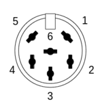
Pinout

| Pin | In | Out | Use |
|---|---|---|---|
| 1 | VIA #2 CB1 | SRQ in (unused) | |
| 2 | GND | ||
| 3 | VIA #1 PA7 | ATN out | |
| 4 | VIA #1 PA0 | VIA #2 CA2 | CLK |
| 5 | VIA #1 PA1 | VIA #2 CB2 | DATA |
| 6 | RESET | ||