RF Modulator

In the early 1980s, dedicated computer monitors were expensive devices. As well, home televisions of that era were rarely equipped with audio/video input jacks. In order to to allow people to use their own television as the VIC-20's display device, Commodore shipped all VIC-20s with an RF modulator. The modulator essentially "broadcasts" (although in closed-circuit) the VIC-20's video and audio output on frequencies corresponding to either VHF channel 3 or 4 (selected by means of a switch on the modulator itself) for NTSC for modulators and UHF channel 36 for PAL modulators (channel selection switch may not be present).
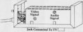
The RF modulator's electronics are contained inside a small rectangular metal box. Running from this box is a wire with a DIN type connector at the end. This connector can be plugged into the VIC-20's video output jack. Also on the metal box is a female RCA connector where one can attach the cable that runs to the GAME-TV switch-box hooked to the rear of the television. This switch-box is in turn attached to the television's antennae terminals or to its 75-Ohm Cable-TV connector and allows a user to manually toggle between broadcast television programs and the VIC-20's display.
While the RF modulator allowed the VIC-20 to be used by more people than could otherwise afford an expensive monitor, it did so at the cost of reduced picture quality. Often RF interference from external sources, lack of fine-tuning or a bad connection resulted in herring-bone interference patterns and audio/video noise (buzzing and sparkles).
Potentiometers inside the VIC-20's RF modulator allow for fine-tuning adjustments to be made to its video output frequency and audio level.
Images
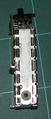
A top view of the second case found inside this Australian PAL RF modulator shows that this case is not held together by screws but rather the plates on either side clip onto the centre.
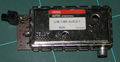
Backside of the Australian PAL RF modulator showing the PCB that is external to the inner case. The PCB is where the lead to the VIC20 is connected to the modulator. Wires from the modulator connect to the PCB.
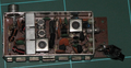
Pulling the case of this (Australian) PAL modulator apart reveals another case.
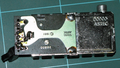
The internal circuit of a Australian PAL RF-modulator.
Schematic of RF-modulator for the PAL television standard.
Potentiometers inside the RF-modulator for making adjustments to video channel tuning & audio level


