Hardware Modifications
Contents
Improving VIC Video
Tweaking video
Some basic video signal adjustments can be made by tweaking a few potentiometers on the VIC-20s motherboard.
Adding an S-Video output
It is possible to greatly improve the VIC-20's video output by adding and S-Video output. This requires a straight-forward, but involved modification to the VIC's motherboard.
Removing vertical patterns & colour phase problems
Vertical Patterns
1. Add a 220 µF Capacitor across the +5V supply to the VIC chip. (You can easily connect between pins 20 + 40 of the VIC Chip).
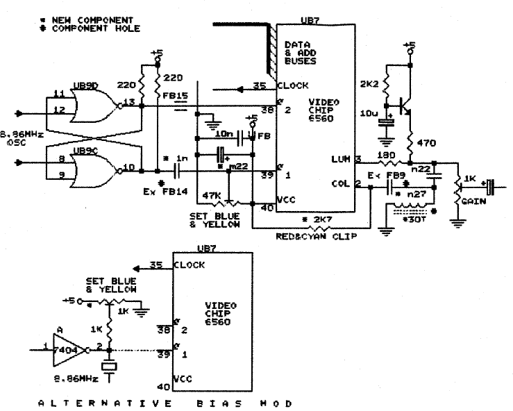
2. For some reason, there are strong 1MHz pulses on the Colour output Pin #2. Replacing the simple colour coupling capacitor for a better high pass C-L-C filter (220pF - 10-50microH - 270pF) does the rest. There is room for these components by removing the simple ferrite bead attached to pin 2 (See schematic below)
Colour Phase
1. Red and Cyan. In most cases the colours are clipped due to an incorrectly biased Colour output stage. Placing a 2.7kΩ (estimate, may vary according to machine) resistor from Colour output pin 2 to +5V track pulls the output voltage up and stops the clipping.
2. Blue and Yellow. These subcarrier levels (not phases) are affected by rebiasing the clock chip to the video chip on pin 39. Ferrite beads links can be removed to add the series capacitor or on some models by rebiasing the incoming clock IC on its pin 2 with a pull up 1kΩ resistor and a pot.
Creating a new Power Supply
The VIC comes with two different power supplies, depending on the date of manufacture.
Old Style two prong 9V
This is used in conjunction with the original model of VIC-20's. The external power supply is a simple 9VAC transformer, with no electronics included inside it.
This unit is typically very reliable but it dissipates a lot of heat as it carries internally a rectifier bridge and a 5V regulator. It is normal for the unit to "buzz" at 60hz lightly.
New Style DIN Brick
The VIC-20 revision C uses a different type of power supply which provides 9VAC and regulated 5VDC. Since the 5V regulator is external with this revision of the VIC-20, it dissipates much less heat and consumes less power.
The power supply of the revision C is similar to the one supplied with the Commodore 64 and uses exactly the same type of connector with same pinout assingment. However, the VIC-20 model is rated for less power so it is not recommended to use a power supply from a VIC on a 64.
People who accidentally or intentionally powered their 64 with the power supply of a VIC-20 revision C often damaged their 64 when the 5V regulator in the power supply fails and outputs excessive voltage resulting in damage to the 64's CMOS DRAM chips.
Doing the opposiste, powering a VIC-20 revision C with a 64's power supply is perfectly safe.
These power supplies are also very susceptible to failure. All electronic components are sealed in epoxy inside the brick and cannot be easily repaired.
However, it is quite simple to create a new power supply for the VIC utilizing the DIN connector from a failed/suspect supply.
Requirements: 1. 9V AC power supply 1.0A (Some older analog modems have this. It has to be AC for timing signals) 2. 5V DC power supply >2A. These are fairly common, most wallwarts provided with internet routers or powered USB hubs meet or exceed these requirements. An old PC-AT power supply will do (the kind with the hard switch).
Pin 6+7: Connect to 9V AC
Pin 2: Connect to negative side of 5V
Pin 5: Connect to positive side of 5V
Known ROM Bugs
RS232 DSR + CTS (Hardware Handshaking)
Hardware Handshaking is broken
EFF4  BIT $9120	<--- these should be $9110 not $9120
F512  LDA $9120
RS232 Read Status
Status Register is lost
FE5D  LDA $0297	Read RS-232 STATUS REGISTER
FE60  LDA #0	     <--- ACC is lost, so we should do
FE62  STA $0297	          LDX #0
FE65  RTS                 STX $0297
RESTOR Kernel call writes to ROM
RESTOR call falls through to VECTOR. However, this causes STA ($C3),Y to occur, writing to ROM. This can cause trouble with certain hardware.
FD52  LDX #$6D    RESTOR entry point
FD54  LDY #$FD
FD56  CLC
FD57  STX $C3     VECTOR entry point
FD59  STY $C4
FD5B  LDY #$1F
FD5D  LDA $0314,Y  fix   LDA ($C3),Y
FD60  BCS $FD64    --->  BCC $FD66
FD62  LDA ($C3),Y        LDA $0314,Y
FD64  STA ($C3),Y
FD66  STA $0314,Y
FD69  DEY
FD6A  BPL $FD5D
FD6C  RTS

