40 and 80 column boards
Contents
Introduction to 40 and 80 column boards for the VIC-20
The VIC-20 was popular but suffered stigma among "serious" computer users (i.e. programmers & researchers) because of its 22-column display, which they felt was too limiting. To remedy this several third party companies released display boards which plugged into the VIC-20's expansion port, thereby giving it the ability to display 40 or 80 columns of text at once.
VTE-40
- Vendor: MSD, Inc.
- Software: 4 KB terminal program (40 column screen)
MR 40/80
MC 6845
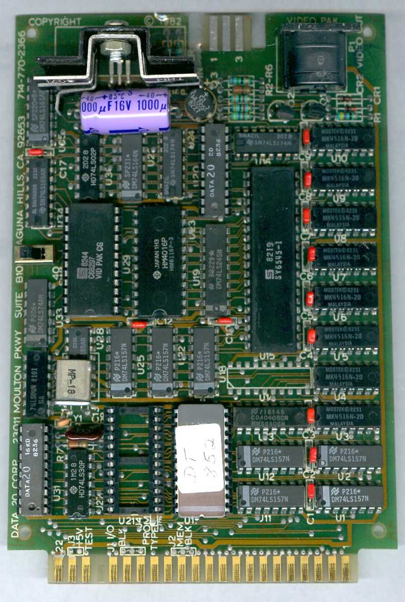
Data 20 Video Pak
Includes 16K, needs extra power supply.
http://www.nemetzpower.de/Denial/Data20-16k.jpg
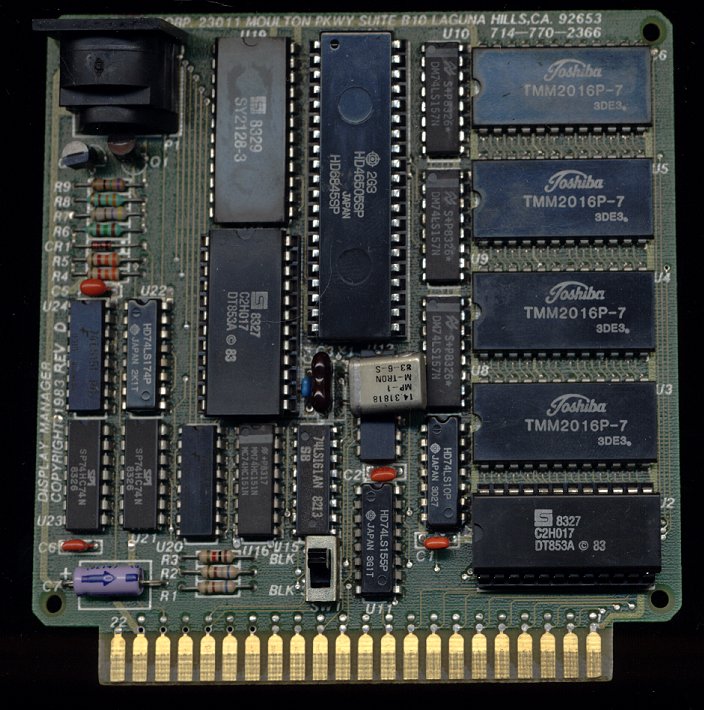
Data 20 Display Manager / Protecto 80 Cartridge

This cartridge takes over the video functions of the VIC, and allows the display of 40 or 80 columns B+W, using its own DIN port.
The VIC chip is still functional, so it is possible to setup a dual monitor system. Regular POKE statements can be used to update the original VIC chip screen.
This cartridge has space for expansion memory (U3-U6), which is populated in the Data-20 8K units. Firmware ROM U2 is a 2316 IC with CS3 (pin 21) modified to be active low. A special adapter is required to read the binary content. Character ROM U18 is also a modified 2316 IC with CS3 (pin 21) active low.
The firmware does not use any special functions of the CRTC chip and is therefore compatible with both the 6545 and the 6845.
 http://www.mainbyte.com/vic20/display_manager.jpg
Technical
Memory Map:
$9BF8 CRT Controller HD6845 / control register
$9BF9 CRT Controller HD6845 / data register
$9BFC Mode Register
     Bit 0: Character set. 0 - upper case, 1 - lower case
     Bit 5: 40/80 Columns. 0 - 40 Columns, 1 - 80 Columns
$A000-$A7FF BIOS ROM
     sys 40969 - 40 column mode
     sys 40972 - 80 column mode
     sys 40975 - return to vic 22 column screen
     sys 40978 - restart 40 or 80 column mode without clearing screen contents
$B800-$BFFF Video RAM
Function Keys:
F1 shift
F2 unshift
F3 Erase to end of line
F4 Erase to end of screen
F6 Screen dump
F8 Terminal mode
Zero 18 40/80 column card


- Vendor: Zero Electronics
- Assumingly same as Kalawsky 40/80 column card.
- Display chip: Motorola MC6845
- 2 KB autostart ROM at $A000
The board has 2716 EPROM for code, 2732 EPROM for fonts, 2016 RAM for screen memory and MC6845 CRT controller to generate video addresses and sync signals. In addition to those there are several TTL logic chips and some passive components. Video output is done through card's own DIN/RCA connector. Both VIC-I and MC6845 screens can be used simultaneusly by directly poking the screen not under kernal control.
Memory addresses
MC6845 address register is at 38912 ($9800).
MC6845 data register is at 38913 ($9801).

Screen memory is located at 43008 ($a800).
Writing to memory is done normally, but reading is done in two steps:
1) first reading dummy value from the correct address, then
2) reading screen contents from 38944 ($9820).
| Power-up/reset keys | |
|---|---|
| RETURN | Use normal display |
| Right shift (can be combined with other keys) | 80 column mode |
| 0 | 25 rows (default) |
| 1 | 24 rows |
| 2 | 23 rows |
| 3 | 21 rows |
| 4 | 19 rows |
| 5 | 17 rows |
| 6 | 16 rows |
| 7 | 15 rows |
| 8 | 14 rows |
| SYS commands | |
|---|---|
| SYS 42997 ($a7f5) | Set screen geometry. "POKE 211 ($d3),height : POKE 243 ($f3),width" first. Height value is from 0 to 7 and matches the corresponding power-up key. The screen won't be centered horizontally. |
| SYS 43000 ($a7f8) | Add VIC-I screen memory to BASIC free memory, gaining 512 bytes. |
| SYS 43003 ($a7fb) | Lock topmost screen row. Up to 7 (40 columns) or 4 (80 column) rows can be locked by repeating the SYS command. |
Links
- Data 20 (web archive)
- Zero 18 software
- File:Mc6845.pdf